


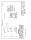

Further disassembly may be accomplished by removing the backplate assembly from its four
mounting standoffs, and laying the two separated assemblies out as illustrated on the “Analyzer
Wiring Diagram”. The diagram is included among the drawings at the rear of the manual.
1.3.6 Circuit Description
: A Micro-Fuel Cell (Class B-2C) is used as the
transducer; its output current is in proportion to the concentration of the oxygen measured. A
current-to-voltage converter, A3, supplies an output voltage, whose level is set by the range
switch to the span pot. A thermistor varies the gain of amplifier A2 as the temperature of the
cellblock changes; this compensates for the change in output of the Micro-Fuel Cell due to
changes in temperature. The output of A2 is shown on the digital panel meter (DPM). Refer to
the schematic diagram.
The batteries are charged when the instrument is connected to the main power supply, and kept
in the off position. The batteries are charged at 80 mAmp, set by resistor R1. In the
measurement mode, amplifier A1b, which floats the ground at the center of the power supply,
controls the power supplied to the amplifier and the DPM.
The synthetic ground amplifier maintains a constant ratio of 1:1 between the negative and
positive power supplies. The constant ratio keeps the offset voltage of the amplifier from
changing as the battery voltage varies up and down. This prevents damage to the Micro-Fuel
Cell, due to oxidation caused by reverse-polarity charging. The synthetic ground is produced by
connecting the non-inverting input of amplifier A1b to the junction of R7 and R8 (which is at the
ground potential); the output of A1b is the synthetic ground. The resulting dual power supplies
have a constant ratio of:
Neg. supply/Pos. supply = R7/R8 = 1.
WARNING
: Caution should be exercised! If the battery is discharged excessively, the battery
cells may be damaged, and this will shorten the life of the battery. Always check the battery
charge before using the instrument.
If the battery voltage should drop to zero while the unit is operating, the FET switch Q1 shorts
the Micro-Fuel Cell; this protects the cell from damage or saturating with oxygen.
-3-
2. SUPPORTING EQUIPMENT AND SERVICES
2.1 Sampling Equipment
: The customer must provide a means of controlling the
pressure and flowrate of the sample gas. For positive pressure applications, TAI suggests a
simple throttle valve, installed in the sample line between the sample point and the analyzer.
The flowrate should be limited to 0.1 to 10 liters/min. IMPORTANT: If a pressure regulator is