


Quickstart Guide Trace Oxygen Analyzer
Teledyne Analytical Instruments 4
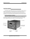
SETUP AND INSTALL
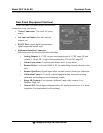
Mount the Analyzer
The Model 3000TA -EU is for indoor use in a general purpose area. It is NOT for hazardous
environments of any type. It is designed for flush panel mounting. Use the four mounting holes—
one in each corner of the rigid frame to panel mount the instrument.
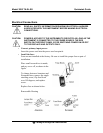
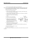
Make Gas Connections
Note: Do not remove plastic caps on VCR fittings, unless you are ready to make
connections.
The analyzer is equipped with 1/4 inch tube fittings, and 6 mm adapters are supplied for
metric system installations.
1. Connect your sample gas to the SAMPLE IN port.
2. Connect a vent line to EXHAUST OUT port.
3. Calibration gases should be tee'd into the sample inlet with appropriate valves.
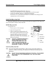
4. Regulate the sample gas pressure between 2 and 50 psig sufficient to keep the front
panel flowmeter reading in an acceptable range (0.5 to 2.0 SLPM). For non-
pressurized sample or very low pressure, (less than 2 psig) vacuum service plumbing
is recommended.
5. If greater sample flow is required for improved response time, install a bypass in the
sampling system upstream of the analyzer input.
6. For optional vacuum application where the sample pressure is at atmospheric or very
low pressure, the instrument should be fitted with the vacuum service option. This
option locates the flow control valve on the exhaust side of the Micro-fuel Cell.
Note: Exhaust connections must be consistent with the hazard level of the constituent
gases. Check Local, State, and Federal laws, and ensure that the exhaust
stream vents to an appropriately controlled area, if required.