


ASSEMBLY INSTRUCTIONS
Before Assembly
NOTE: Carefully inspect all cartons for shipping damage
before unpacking. If damage is found, contact your
shipper or Tanita Corporation immediately. Claims must
be filed with the shipper as soon as possible after receipt
of the damaged package.
One carton containing: Handlebar with wheels, platform,
and 2 parts boxes. (Model 4500 only—separate insert
with ramp and front and side rails.)
One parts box containing: AC adaptor and storage
bracket, C-clamp, twelve (12) locknuts, three (3) cable
clamps, hex key, hex bolts, and sheet of adhesive labels.
Another small box containing: The electronic
control panel box.
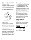
IMPORTANT: After assembling the scale, charge the
battery in the control panel box using the procedure
under “Charging the Battery” on page 3. This will restore
any power lost during storage and shipment.
Tools Needed: Adjustable wrench or 7/16" socket or
open-end wrench.
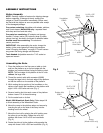
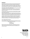
Assembling the Scale
1. Place the platform on the floor near a table or chair
and turn the platform up on its front edge with the
platform top (matted surface) facing the table or chair.
NOTE: The front edge of the platform is the 24" side
without the large hole.
2. Thread the control cable with connector (63826)
through the large hole in the back edge of the platform
so that the cable is on the outside of the platform.
3. While resting the top portion of the handlebar on the
table or chair, fasten the handlebar to the platform with
eight 1/4-20 x 5/8" bolts and nuts. (Fig. 1)
4. Screw a leveling foot into each corner of the platform
bottom. Leave 1/4" of thread showing.
5. Put the scale back on its feet.
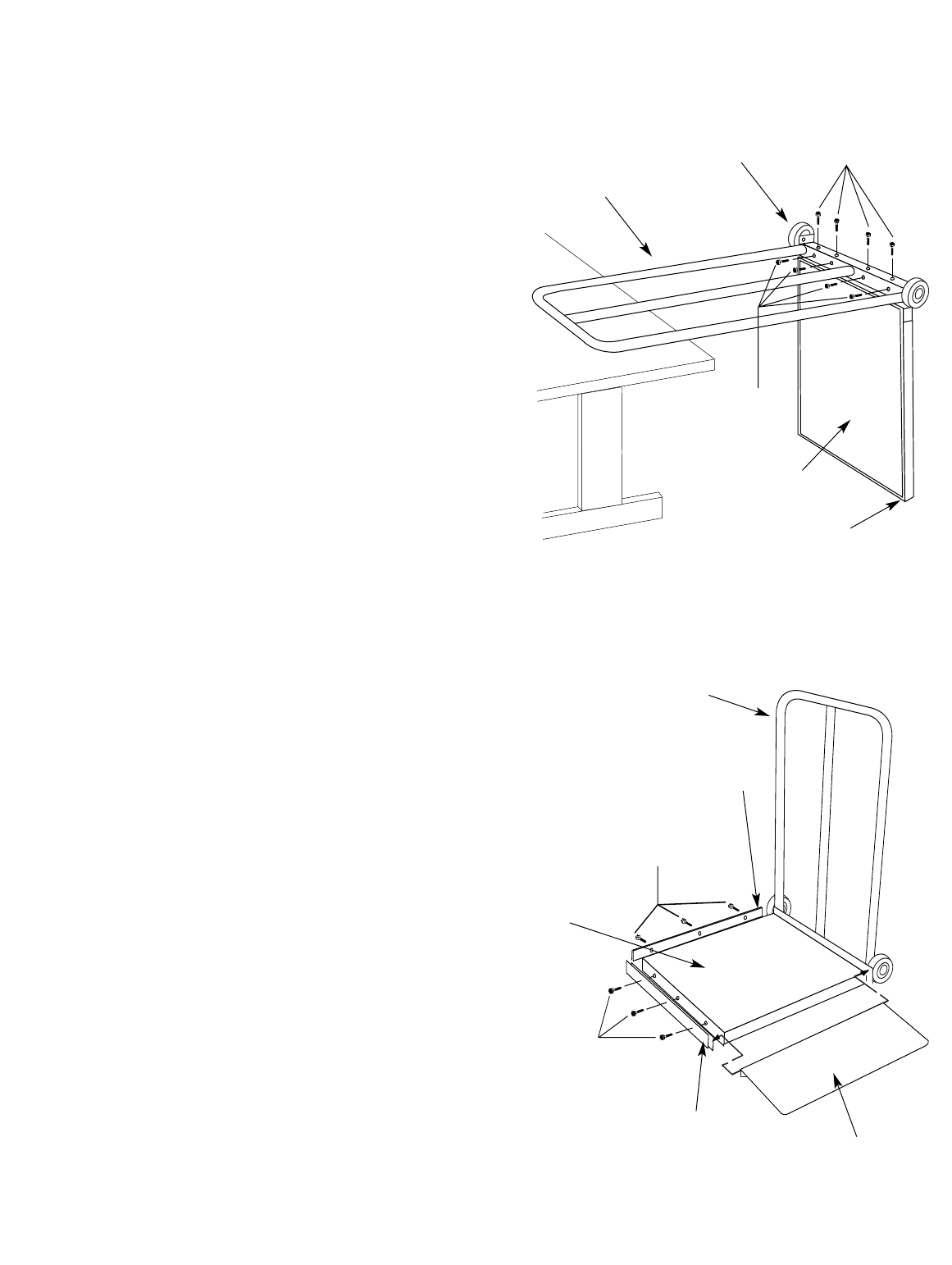
Model 4500 Wheelchair Scale Only: Follow steps 6-8
to finish assembly of the Wheelchair Scale.
6. Mount the ramp to the platform edge, and secure by
inserting the pin on the side of the ramp into the
bushing next to the wheel.
7. Mount the front rail by placing the rail’s bushing over
the other pin on the ramp. Fasten the rail to the
platform with three 1/4-20 x 5/8" hex head bolts.
(Fig. 2)
8. Fasten the side rail to the platform side opposite the
ramp with three 1/4-20 x 5/8" hex head bolts. (Fig. 2)
2
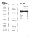
Fig. 1
Fig. 2
Handlebar
63949
Wheel
63970
1/4-20 x 5/8"
Allen Bolts
1/4-20 x 5/8"
Allen Bolts
Platform
1/4-20 x 5/8"
Hex Bolts
Hex Bolts
Front Rail
Rubber Mat
63881
Ramp
(Model 4500 only)
Handlebar
63949
Side Rail
Rubber Mat
63881