


ASSEMBLY INSTRUCTIONS
Before Assembly
NOTE: Carefully inspect all cartons for shipping damage
before unpacking. If damage is found, contact your
shipper or Tanita Corporation immediately. Claims must
be filed with the shipper as soon as possible after receipt
of the damaged package.
One carton containing: Folding platform
One parts box containing: AC adaptor, four (4)
threaded feet, two (2) sheets of adhesive labels,
and two (2) elastic cords.
Another small box containing: The electronic
control panel box.
Tools Needed: None
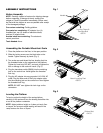
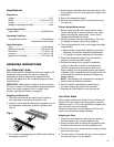
Assembling the Portable Wheelchair Scale
1. Place the platform on the floor, in the open position.
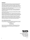
2. Slide the locking screw over the black tabs on the
handle. Tighten securely by hand. (Fig. 1)
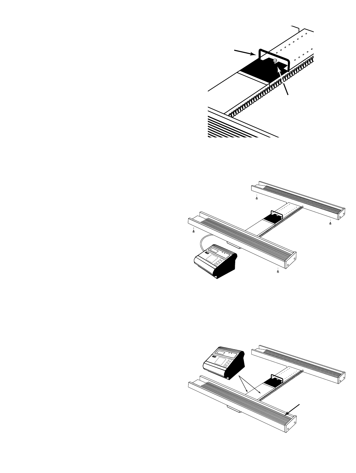
3. Turn scale over and thread the four leveling feet into
the threaded holes on the underside of the platform.
Tighten by hand only. DO NOT use tools to tighten the
feet or damage to the scale will result. (Fig. 2)
4. Plug the transducer cable (63826) into the matching
jack on the control box. Hand tighten the threaded
lock ring.
5. Plug the AC adapter into any grounded 110-120V AC
outlet. Plug the other end of the 3-pin adapter cable
into the matching jack on the control box. Hand tighten
the threaded lock ring.
NOTE: DO NOT over-tighten the lock rings on the
connectors.
Leveling the Platform
To level or adjust the height of the scale platform,
carefully tilt the scale and turn the leveling feet either into
or out of the platform underside.
NOTE: Adjust platform height so it does not touch floor
or carpet. An incorrect weight reading will result if the
ramp touches the floor or carpet.
Z
E
R
O
P
O
U
N
D
S
K
IL
O
S
O
N
O
F
F
P
o
u
n
d
s
K
i
l
o
s
w
w
w
.
t
a
n
i
t
a
.
c
o
m
P
u
s
h
“
O
N
”
b
u
t
t
o
n
a
n
d
w
a
i
t
u
n
t
i
l
z
e
r
o
a
p
p
e
a
r
s
b
e
f
o
r
e
s
t
e
p
p
i
n
g
o
n
s
c
a
l
e
W
E
I
G
H
T
Z
E
R
O
P
O
U
N
D
S
K
I
L
O
S
O
N
O
F
F
P
o
u
n
d
s
K
ilo
s
w
w
w
.
t
a
n
i
t
a
.
c
o
m
P
u
s
h
“
O
N
”
b
u
t
to
n
a
n
d
w
a
it
u
n
t
il
z
e
r
o
a
p
p
e
a
r
s
b
e
f
o
r
e
s
te
p
p
i
n
g
o
n
s
c
a
le
W
E
IG
H
T
2
Fig. 1
Fig. 2
Locking Screw &
Carriage Bolt
64012
Handle
Attach Leveling Feet
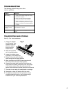
63879
Rubber Mat
64013
Fig. 3