


The dual engine synchronizer is designed to indicate
engine synchronization extremely accurately
when the
speeds of the two engines are compared to each
other. Engine synchronization may be difficult at idle
speeds. For proper operation, both engines must be
of the same type, have the same number of cylinders,
and have similar ignitions. Malfunctioning ignition
systems or high speed "point bounce" will result in
inability to sync properly.
1. Location: The synchronizer should be located at
least 18" from a magnetic compass. Some
interference (erratic operation)
may be noticed on the
synchronizer during radio transmissions. This will
neither damage nor degrade it's performance.
2.
Be certain to use stranded, insulated wire not
lighter than 18AWG that is approved for marine use. It
is recommended that insulated wire terminals,
preferably ring type, be used on all connections to the
gauge, except the light which requires a 1/4" female
blade terminal.
3. Cut a 3-3/8" dia hole in the dash and mount the
gauge with backclamp supplied.
4. Using a small screwdriver, SLIGHTLY depress
and turn the selector switch on the back of the
synchronizer to the correct position to match the
engine application. (See label on the side of the
synchronizer.) Depressing the switch too hard may
cause damage to gauge! Be sure the selector switch
has locked into the detent at the correct position by
slightly rotating the switch
back and forth with the
screwdriver.
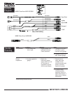
5. If this gauge kit has been supplied with a three
prong connector, slide the connector over the three
instrument studs. Be sure the gray, yellow, and black
bullets are connected to the gray, yellow, and black
wires of the main engine harness.
6.
Connect the gray extension lead stud connector
to the positive (+) post of the synchronizer and plug the
bullet end into the gray wire of the main engine
harness.
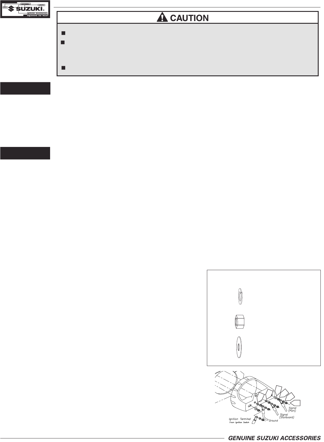
7. Connect the yellow extension lead stud
connector to the STARBOARD signal (SIG) post
terminal of the synchronizer and plug the bullet into
the yellow wire of the main engine harness.
8. Connect yellow/red extension lead stud
connector to the PORT signal (SIG)
post terminal of
the synchronizer.
9.
Connect the black extension lead stud
connector to the negative (-) post of the synchronizer
and plug the bullet end into the
black wire of the main
engine harness.
10. Connect the GREEN/ORANGE extension
lead to the blade terminal adjacent to the twist-out
light assembly to the positive “+” side of the
instrument lighting circuit and the bullet end to the
boat l
ighting circuit. No separate ground is required
for the lighting. Reconnect the battery.
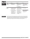
11.
Calibration: This gauge has been calibrated
at the factory, and should never need adjustment.
However, If
you are experiencing problems refer to
the Calibration section at the end of this manual.
12.
NOTE: To change the light bulb, twist tan
socket assembly one-eighth turn counterclockwise
until it pops out. Bulb pulls straight out of socket
assembly. It is a GE No.194 instrument lamp.
Mounting Hardware Kit
A
x 6
x
6
B
C
x 2
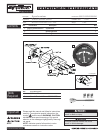
Description
Installation
Disconnect battery during installation.
Tighten nuts on backclamp only slightly more than you can tighten with your fingers.
Six inch-pounds of torque is sufficient. Over tightening may result in damage to the
instrument and may void your warranty.
Gasket cement or other adhesive is not required to secure tubing to fittings.
B
B
A
A
A
C
B
A
C
GRAY
BLACK
YELLOW
If so equipped