


930570 Rev. C
IX. Set-up, Adjustment & Use
33
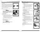
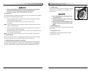
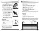
O. WHEEL LOCKS
Wheel locks are installed by Sunrise when requested on
the Quickie S-626.
1. Mounting
The wheel lock mounts to the motor mount.
Use a torque setting of 100 in./lbs when adjusting
wheel locks.
a) Loosen bolts (D).
b) Slide mounting bracket toward rear wheel until
clamp embeds into tire to prevent wheel move-
ment when in locked position.
c) Tighten screws.
NOTE– Wheel lock adjustment will be done through the
drive-wheel spokes.
P. SUSPENSION
Note– Equivalent adjustments should be done to both
the right and left suspension element.
It is important to properly adjust the pre-load and damp-
ing to ensure proper comfort and control for the rider.
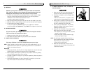
1. Pre-Load Adjustment
With the rider seated in the chair and with batteries
installed, insure that the main horizontal member of the
base frame is parallel to the ground. If it is not parallel,
adjust spring collar (B) in either direction to adjust. If
the rear of the base frame is lower than the front, adjust
the spring collar clockwise when viewed from the rear of
the chair. If the rear of the base frame is higher than
the front, adjust the spring collar counter-clockwise
when viewed from the rear of the chair.
The spring pre-load ring should never be
adjusted so that the shock spring is less than
four inches long with the chair unoccupied and
the batteries installed. Too much spring pre-
load may cause the spring to fail.
IX. Set-up, Adjustment & Use
930570 Rev. C
32
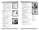
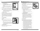
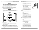
L. BACKREST
A backrest angle-adjustment is standard on the Trax
Seat Frame.
1. Adjustment on Trax Seat Frame
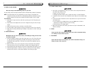
a) Remove the securing bolt (A) on the sides of
the backrest hinge plate.
b) Set at desired angle. There are ten holes (in 4º
increments) to choose from.
c) Reinstall the front bolt and tighten both bolts
securely.
M. SEAT DEPTH
The seat depth can be adjusted continuously along the
seat rail.
1. Seat Frame Depth Adjustment
a) To adjust, loosen the four bolts (B) from each
side of the backrest pivot plate.
b) Reposition the backrest to the desired position.
c) Retighten bolts on each side of the backrest
pivot plate.
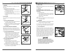
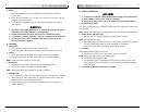
N. SEAT HEIGHT AND ANGLE ADJUSTMENT
Adjusting the seat height can be done both at the
front and the rear of the seat. Seat angle can also be
varied through front and rear seat height adjustments.
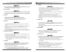
1. Front Seat Height Adjustment.
a) Remove bolt (A) in the seat height strut (B).
Adjust the upper and lower tube until the
desired front seat height is achieved. Each
upper hole is 1" apart. Each lower hole is 1/2"
apart. This allows 1/2" seat height increments.
b) Replace the bolt and secure the locknut.
2. Rear Seat Height Adjustment
a) Remove bolt (C).
b) Loosen bolt (D), but do not remove.
c) Adjust seat height to match one of three posi-
tioning holes (G). Each hole is 1" apart.
d) Refasten bolt (C) and retighten bolt (D).
e) To achieve 1/2" increments adjust position bolt
(E) to either hole (F) and refasten.
A
B
move back
or forward
loosen all 4
D
A
B
E
F
D
C
G
C
B