


930478 Rev. A
V. Set-up, Adjustment & Use
9
D. FOAM BACK
Secure the foam and cover to the shell.
To secure the back foam and cover on the Solid Seat Back, slide the top edge
of the cover over the top lip of the shell. Press the back in place against the
shell.
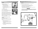
E. SEAT TILT ADJUSTMENTS & DRIVE LOCK-OUT
1. Maximum Tilt Angle
Maximum tilt angle can be adjusted to a limit of 50°.
a) Remove access cover on the actuator housing.
b) Position the most forward switch such that the actuator shuts down when
the desired maximum tilt is achieved.
c) Tighten the switch to the track, and replace the cover on the actuator
housing.
2. Drive Lock-out Angle
The drive lock-out angle is adjustable.
a) Tilt the seat back at least 15°-20°.
b) Remove the access cover on the actuator.
c) Adjust the middle limit switch until the desired lock-out position is
achieved.
d) Replace the access cover on the actuator housing.
NOTE– The drive lock-out should be set such that the chair cannot be driven with the
seat tilted to an angle of greater than 15°.
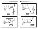
F. SEAT DEPTH
The seat depth can be adjusted in one inch increments.
1. Seat Frame Depth Adjustment
a) To adjust, remove the two bolts (C & D p. 10) from each side of the backrest
pivot plate.
b) Reposition the backrest to the desired position.
Note: Substitute Bolt (D) with rear back rest pivot plate bolt (C) for 18" seat
depth.
c) Replace and retighten bolts on each side of the backrest pivot plate.
V. Set-up, Adjustment & Use
930478 Rev. A
8
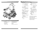
B. SOLID SEAT BACK & LATERAL THORACIC SUPPORTS
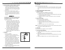
1. To adjust the height of the lateral support
mount, loosen the adjustment screw until the
receiver slides freely on the back posts. Tighten
the adjustment screw when the proper height is
determined.
2. Assess and fit the lateral thoracic supports.
Assess client for proper positioning of the later-
al thoracic supports. Each support is indepen-
dent and may be adjusted for your client’s clini-
cal need.
A minimum of 1" (2.5 cm) of clearance should
exist between the top of the lateral support
and the user’s arm pit.
a) To adjust the height, angle or width of the
lateral thoracic support pads, loosen the top
bolts and slide to correct width. Tighten bolt
to bolt plate. If more adjustment is neces-
sary, loosen the internally mounted bolts,
and slide in the track to the desired height
and width. The angle is obtained by tilting
the bracket as needed. Tighten the bolts.
b) To adjust the depth of the lateral thoracic
pads, turn the middle bracket so that the
slots are on side. Adjust to desired depth. Re-
tighten the bolts.
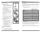
C. HEADREST
1. Mounting a headrest.
The Solid Seat Back has a headrest plate
mounted to it. Care should be taken to use the
proper screw length when mounting.
2. To position the headrest use the double clamp
and the collar clamp (B,C,D) to obtain the
proper height and distance. For clamp B use a
3/32 Allen set screw (A) and a 3/16 Allen cap
screw. Clamp B positions the headrest forward
and aft. However, due to the vertical movement
of this adjustment, collar clamp D will have to
be moved in conjunction.
3. Retighten both the 3/16 Allen and the set screws
(A) with a 3/32 Allen wrench.
A
A
B
B
C
D