


10 ► TT46 User Manual
OPERATION
PREOPERATION PROCEDURES
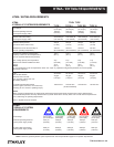
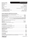
CHECK HYDRAULIC POWER SOURCE
1. Using a calibrated owmeter and pressure gauge, check
that the hydraulic power source develops a ow of 4-6
gpm/15-23 lpm at 1500-2000 psi/106-140 bar. For TT46233
Model, 7-10 gpm/26-38 lpm.
2. Make certain the hydraulic power source is equipped
with a relief valve set to open at 2200-2300 psi/152-159 bar
minimum. Maximum full ow pressure not to exceed 2500
psi/172 bar.
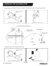
INSTALL TOOL BIT
1. Remove the two capscrews that hold the bit keeper to
the lower body or on some models remove the two hex
head capscrews, outer springs, and nuts that hold the bit
keeper to the lower body.
2. Remove the two pair of bit-retaining spring guides and
spring or on some models the one pair of bit guides from
the bit keeper.
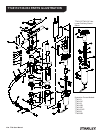
3. Insert the hex end of the bit as far as possible through
the small end of the bit keeper (see parts list illustration).
4. Install the coil spring on the bit hex ange. Install a
spring guide pair on each end of the spring. On some mod-
els only the one pair of bit guides need to be installed and
no spring.
Note: There are two types of spring guides. Each of the
two types must be installed in matched pairs. The pair used
at the top of the spring have a at end that goes against the
bit collar.
Carefully install the bit keeper so that the lower spring
guide ts into the lower keeper bore and that the upper at
end of the guide rests against the bit ange.
5. With the bit pulled down into the keeper, insert into the
tie tamper hex, then press the bit keeper up against the
lower body.
6. Tighten both capscrews or on some models install the
hex head capscrews, outer springs, and nuts and tighten
securely.
CONNECT HOSES
1. Wipe all hose couplers with a clean lint-free cloth before
making connections.
2. Connect the hoses from the hydraulic power source to
the tool tting or quick disconnects. It is a good practice to
connect the return hose rst and disconnect it last to mini-
mize or avoid trapped pressure within the tool.
3. If hose couplers are used, observe ow indicators
stamped on hose couplers to be sure that oil will ow in the
proper direction. The female coupler is the inlet (pressure)
coupler.
NOTE:
The pressure increase in uncoupled hoses left in the
sun may result in making them difcult to connect.
When possible, connect the free ends of operating
hoses together.
TOOL OPERATION
1. Observe all safety precautions.
2. Install the appropriate tool bit for the job if not already
installed.
3. Place the tamper on the surface to be compacted.
The Tamper will rise quickly when rst turned on. Do not
stand over or place any part of your body on top of the
tamper. Wear safety shoes.
Note:
Partially pressing the trigger allows the tool to run at
slow speed, making it easier to start or control.
5. Guide the tamper using both hands.
COLD WEATHER OPERATION
If the tie tamper is to be used during cold weather, preheat
the system hydraulic uid at low engine speed.
When using the normally recommended uids, oil uid
temperature should be at or above 50° F/10° C (400 ssu/82
centistokes) before use.
Damage to the hydraulic system or tie tamper can result
from use with oil that is too viscous or thick.
WARNING