


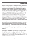
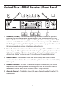
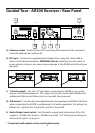
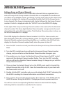

6: EDIT Control – This rotary encoder control knob/switch is used to control and set
several menu functions and parameters displayed in the LCD display and it is also
used to preform the automatic Channel Scan.
7: Power Switch - Use this to turn the AR300 power on and off. When the receiver is
on, the LCD backlight is lit.
8: IR Transmitter – During “IR SET” an Infrared light is used to set the transmitter
channel.
9: RF Meter – 10-segment bar meter used to display the level of the radio frequency
reception.
10: LCD Display – The 47mm x 17mm backlit display show information for Frequency,
Channel, Group, Absolute Channel, Anntena, AF, RF, Scan, and IR Set.
11: AF Meter - 10-segment bar meter used to display the amount of the audio input
level.
12: Level control - This knob sets the level of the audio signal being output through
both balanced output connectors on the rear panel (see C and D on page 12 in
this manual). Reference level is obtained when the knob is turned fully clockwise
(to its “10” setting).
Guided Tour - AR300 Receiver / Front Panel
5