


27Victory
ASSEMBLY
1. Pull up on the manual freewheel lever. See VI. De-
scription. Putting your Victory in freewheel may make
it easier for you to maneuver the rear section because
the drive wheels are free to turn.
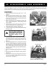
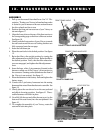
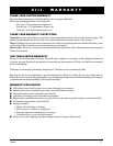
2. Position the front and rear sections of your Victory as
shown in figure 17.
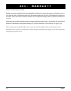
3. Align the lower slots on the rear of the front section to
the corresponding pegs on the front of the rear section.
See figure 18.
4. Gently push the front section of your Victory towards
the rear section until the curved locking brackets are
fully connected onto the rear pegs.
5. Insert the ball detent pin.
6. Place the cam locks in the locked position. See figure
19.
7. Raise the tiller to the upright position by turning the
tiller adjustment lever until it is loose. Raise the tiller to
the desired position. Verify that the tiller release but-
tons are reengaged, and tighten the tiller adjustment
lever.
8. Insert the large, white, 9 pin connector (located on the
harness coming out of the Victorys front section) to
the connectors mating socket (found near the front of
the Victorys rear section). See figure 15.
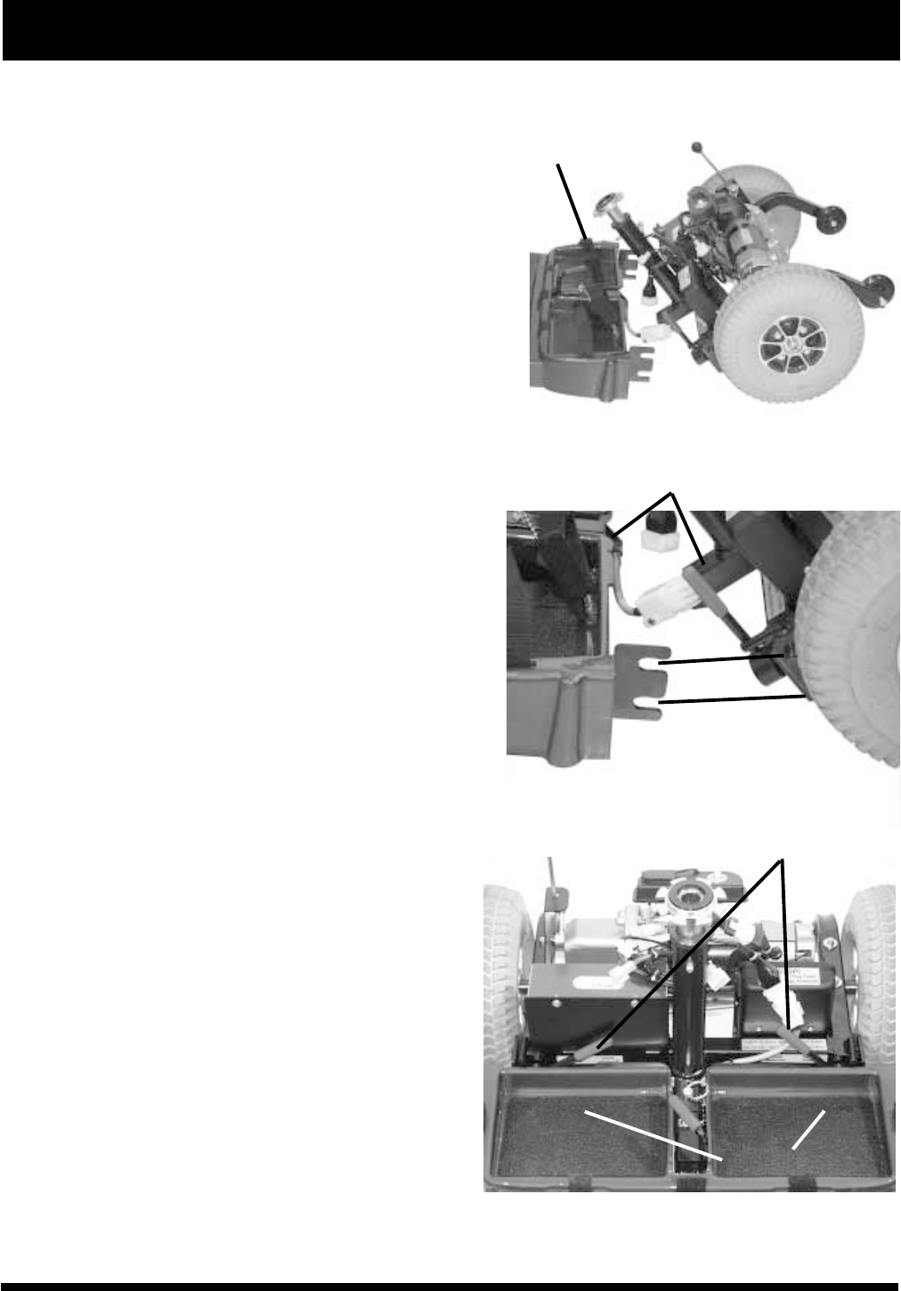
9. Place the batteries in the battery wells and tighten the
battery straps.
10. Connect the 2-pin battery harnesses into the mating
harnesses that extend from the electronic controller. See
figure 14.
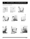
11. Gently place the rear shroud over the seat pedestal
and slide it down into position. See figure 10. The re-
usable fasteners will hold it in place.
12. Carefully lift the seat and slide the seat post (on the
bottom of the seat frame) into the seat pedestal. See
figure 10.
13. To complete the assembly of your Victory, rotate the
seat until it locks into place.
FIGURE 17. FRONT AND REAR SECTIONS
FRONT FRAME HANDLE
CONNECT FRAME HALVES HERE
FIGURE 18. FRAME LOCK
FIGURE 19. FRAME CAM LOCKING
LEVERS
LOCKED POSITION
BATTERY WELLS
IX. DISASSEMBLY AND ASSEMBLY
IX. DISASSEMBLY AND ASSEMBLY