


32 www.pridemobility.com Rally/RevF/September 03
Always disassemble or assemble your scooter on a level, dry surface with sufficient room for you to work and
move around your scooter. Keep in mind that the disassembled sections of the scooter take up more floor space
than the assembled scooter.
I X . DISASSEMBLY AND ASSEMBLY
DISASSEMBLY
1. Remove the key from the key switch. See V. Your Rally.
2. Push down on the manual freewheel lever. See V. Your Rally. Putting your scooter in drive mode may make
it easier for you to maneuver the rear section because the drive wheels are stabilized.
3. Lift the seat up and off of your scooter.
4. Gently lift the rear shroud off of your scooter. The rear shroud is held in place with a reusable fastener.
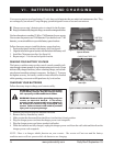
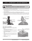
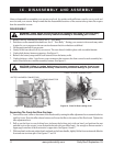
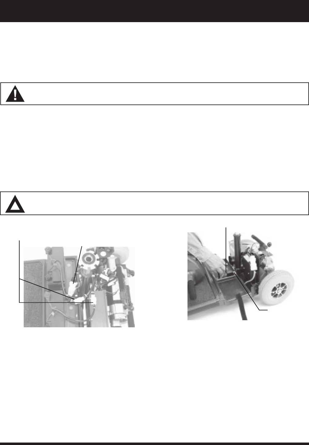
5. Unplug both battery harness connectors. See figure 15.
6. Remove the battery straps and lift both batteries from the battery wells.
7. Unplug the large, white, 9-pin front-to-rear connector that connects the front control console assembly har-
ness to the electronic controller assembly harness. See figure 15.
CAUTION! Failing to unplug both battery harness connectors and the front-to-rear
connector prior to further disassembly could result in permanent damage to your scooter.
WARNING! Lifting weight beyond your physical capability may result in personal injury.
Ask for assistance when necessary while disassembling or assembling your scooter.
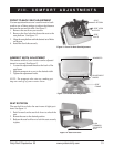
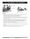
Figure 16. Front-To-Rear Locking Lever
Separating The Front And Rear Sections
1. Lower the scooters tiller to the center of the floorboard by turning the tiller adjustment lever counterclockwise
until it is loose. Press the tiller release buttons and lower the tiller to the center of the floorboard. Tighten the
tiller adjustment lever.
2. Pull up on the front-to-rear locking lever (releases the locking pin) with one hand, and push on the seat
pedestal to pivot the scooters rear section backward with your other handfar enough so the rear sections
upper pegs come free of the front sections upper slots. See figures 16 and 17.
3. With one hand on the seat pedestal and one hand on the frame handle, slightly lift the front section and slide the
front and rear sections apart. See figures 17 and 18.
FRONT-TO-REAR CONNECTOR
Figure 15. Battery Harness Connectors/
Front-to-Rear Connector
BATTERY HARNESS CONNECTORS
FRONT-TO-REAR LOCKING LEVER
LOCKING PIN