


10
www.pridemobility.com Outlander Series
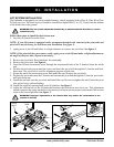
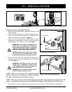
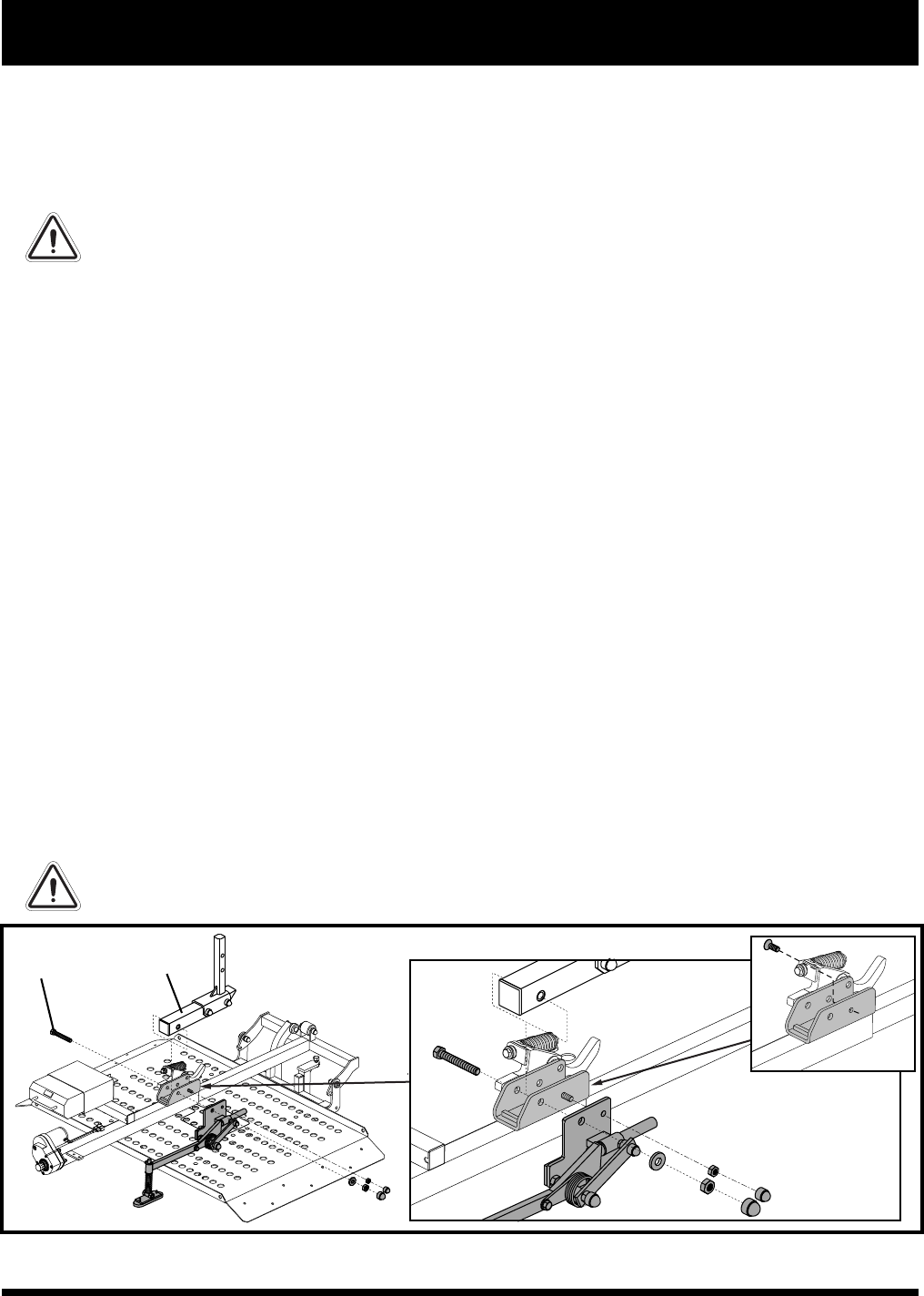
PIVOT
BOLT
PIVOT
TUBE
III. INSTALLATION
LIFT SYSTEM INSTALLATION
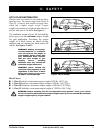
The Outlander is designed to be easily installed into any vehicle equipped with a Class II, Class III or Class
IV hitch receiver. The hitch receiver should be installed no higher than 21 in. (53.34 cm) from the bottom
of the hitch tube to the ground.
WARNING! The lift system should be installed by an authorized Pride Provider or service
technician only.
Follow these steps to install the lock-down arm:
1. Lay the lift system flat on the floor.
NOTE: If your lift system is equipped with a permanent threaded stud, removal of the pivot tube and
pivot bolt is not necessary for lock-down arm installation. See figure 4.
2. Apply power to the lift until there is enough clearance to remove the pivot bolt. See figure 4.
NOTE: If the pivot bolt does not remove easily, apply power to the lift and make a slight adjustment to
the angle of the pivot tube. Repeat as necessary.
3. Remove the pivot bolt. Keep hardware for reassembly.
4. Remove the pivot tube. See figure 4.
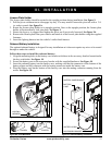
5. Insert the lift arm securement screw through the countersunk hole of the U-bracket (from the inside
out).
6. Position the lock-down arm onto the screw and insert the pivot bolt through the U-bracket and lock-
down arm. The pivot bolt is used for alignment purposes at this time.
7. Secure the nut to the securement screw and install the cap. Remove the pivot bolt.
8. Position the pivot tube onto the U-bracket and reinsert the pivot bolt through the U-bracket, pivot tube,
and lock-down arm.
9. Install the nut back onto the pivot bolt and install the cap. Do not overtighten the nut. Ensure the pivot
tube pivots freely without binding.
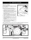
10. Attach the supplied warning label
to the lift platform.
See figure 5.
11. Adjust the tension bolt on the H-frame that actuates the lock-down arm clevis pin. This adjustment
should compress the spring on the lock-down arm pivot foot to ensure proper securement of the scooter
when in the stowed position. See figure 5.
WARNING! Improper adjustment of the tension bolt may affect the securement of the
scooter to the lift!
Figure 4. Lock-down Arm Installation