


Jazzy Select 14Series www.pridemobility.com 19
III. YOUR POWER CHAIR
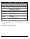
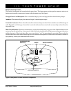
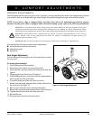
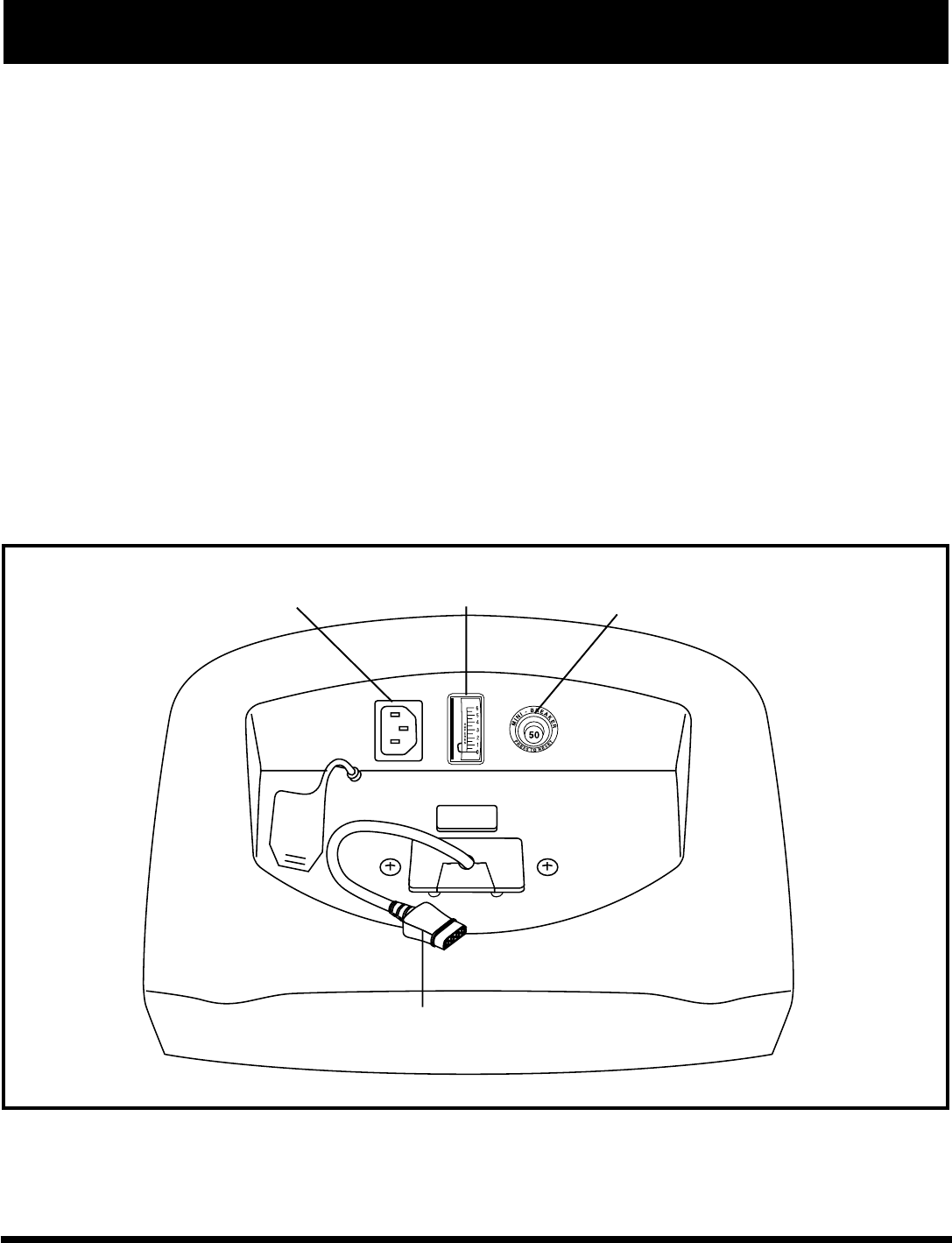
CONTROLLER CONNECTOR
CHARGER POWER CORD
RECEPTACLE
Electrical Components
The electrical components are located inside the power base. The charger power cord receptacle, ammeter, main circuit
breaker, and controller connector are located on the electronics tray. See figure 6.
Charger Power Cord Receptacle: This is where the charger power cord plugs into the onboard battery charger.
Ammeter: The ammeter displays the onboard charger’s current output in amps.
Controller Connector: This is where the controller connects to the power base. Each controller uses a different type of
cable. Regardless of which type of controller is used, the cable must be secured to the seat assembly and not allowed to
drag on the floor.
Main Circuit Breaker: The main circuit breaker is a safety feature built into your power chair. When the batteries and
motors are heavily strained (e.g., from excessive loads), the main circuit breaker will trip to prevent damage to the motors
and the electronics. If the circuit trips, allow your power chair to “rest” for approximately one minute. Then, push in the
circuit breaker button, turn on the controller power, and continue normal operation. If the main circuit breaker continues to
trip repeatedly, contact your authorized Pride Provider.
MAIN CIRCUIT BREAKER
AMMETER
Figure 6. Jazzy Select 14 Series Electronic Components