


Basic Operation Instructions 13
www.pridemobility.com GC2 Controller
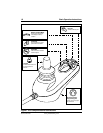
Battery Condition Meter
The battery condition meter consists of five LEDs arranged in an arc over the on/off
and horn keys. See figure 1. When functioning as the battery condition meter, this
indicates the status of the electrical system using LED codes. For example, as the
battery voltage drops, the number of LEDs reduces from right to left. When the battery
capacity drops to 10% or below, the left red LED will flash.
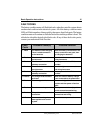
Battery condition meter codes are as follows:
Left Red LED Flashing Slowly or Steady: Battery charge is low; Charge
the batteries as soon as possible.
Red and Yellow LEDs Flashing: Battery charge is low; Charge the batteries
overnight.
Step up of LEDs: The controller is in programming, inhibit, or charging mode.
All LEDs Flashing Quickly: The joystick was not in the center position
when the power was switched on, or the controller system detected a fault;
Refer to the Fault Code Table.
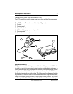
CONTROLLER COMMUNICATION CONNECTOR
The controller communications connector provides the GC2 with a connection to the
power module.
MANDATORY! Prevent controller harness damage! Avoid routing
the controller harness on the outside of the armrest pad. Route
the harness under the armrest or toward the inside of the armrest
pad. Use correct tie-down points for the controller harness to
prevent the harness from getting caught in the drive tires, pinched
in the seat frame, or damaged when passing through doorways.
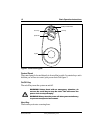
Speed Dial
The GC2 controller provides a speed dial to control the speed of the power chair.
See figure 3.
To change the speed:
1. Push the on/off key to power on the chair and the controller.
2. To increase your speed, turn the speed dial clockwise.
3. To decrease your speed, turn the speed dial counterclockwise.
NOTE: We recommend that the first few times you operate your power
chair, you set the speed to the slowest setting until you become familiar
with your new power chair.