


26 www.pridemobility.com Jazzy 1143 Ultra
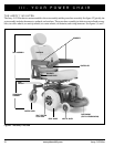
V. COMFORT ADJUSTMENTS
COMFORT ADJUSTMENTS
After becoming familiar with your power chair’s operation, you may find the need to make some adjustments to increase your
comfort, such as seat height and angle, armrest angle, foot platform height and angle, and controller position. If your power chair
is equipped with a medium-back, a high-back, a reclining seat, or a power elevating seat, refer to the following information.
NOTE: If your power chair is equipped with an optional seating system, refer to the information provided in
separate manuals.
WARNING! If your power chair was configured by your authorized Pride Provider, please consult your
healthcare professional before changing the seat position or making any other adjustment. Some
adjustments may degrade your power chair’s performance and safety by changing its center of gravity.
WARNING! Some power chair components are heavy. You may need assistance to lift or carry
them. Please refer to the specifications table for specific component weights before you
disassemble the power chair.
WARNING! Remove the occupant from the power chair before making any adjustments.
You may need the following to make comfort adjustments:
! metric/standard socket set and ratchet
! adjustable wrench
! thread lock
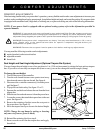
Seat Height and Seat Angle Adjustment (Optional Trapeze Bar System)
You can change the seat height to one of two positions in 1-in. (2.54 cm) increments by raising the front and rear trapeze
bars. If you raise or lower only one trapeze bar (front or rear), you can also change the seat base angle (dump).
To change the seat height:
1. Turn off the power to the controller.
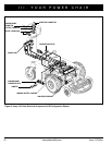
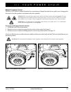
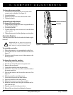
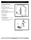
2. Turn the rear shroud fasteners one-quarter turn in any
direction and remove the rear shroud. See figure 6.
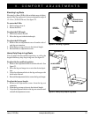
3. Disconnect the controller connector(s) from the power
pod. See figure 7.
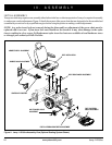
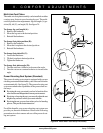
4. Flip up the seat latch safety. See figure 12 or 13.
5. Squeeze the seat latch and release the seat from the front
trapeze bar.
6. Slide the seat forward and remove it from the power base.
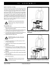
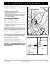
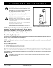
7. Loosen the screws that attach the trapeze bars to the seat
posts. See figure 14.
8. Remove the retaining clips that secure the seat posts to
the power base. See figure 14.
9. Move the trapeze bars up or down to the desired height.
NOTE: Change the seat dump by raising or lowering
only one set of towers (front or back).
10. Reinstall the retaining clips from step 8.
11. Remove each screw from the trapeze bars and apply
thread lock.
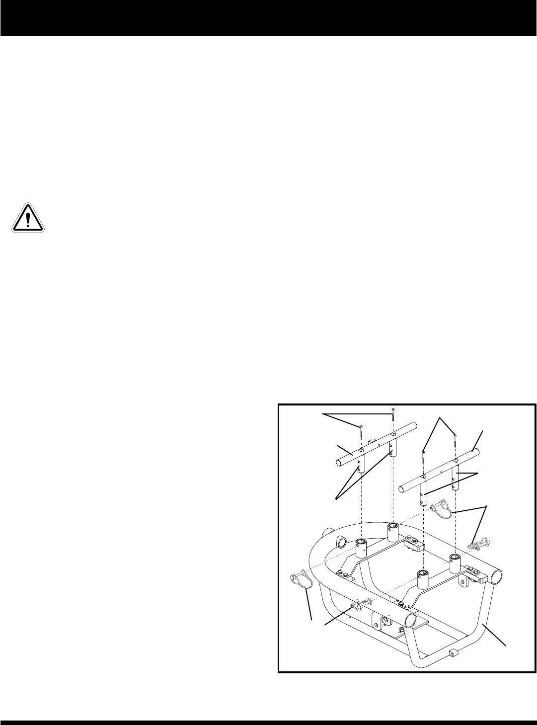
TRAPEZE BAR
RETAINING
CLIPS
POWER BASE
FRAME
SCREWS
SEAT POSTS
Figure 14. Trapeze Bar Location (Optional)
SCREWS
TRAPEZE BAR
SEAT POSTS
RETAINING
CLIPS