


C417M-M (2/06) 5
Installation
The following parts are supplied:
1 Enclosure with attached mounting cradle
1 3/16-inch Allen wrench
1 5 mm Allen wrench
2 1/4-20 x 1/2-inch screws
2 Appleton explosionproof sealable fittings
1 Desiccant bag
1 Sealing instructions for fittings (C903M-A)
1 Service kit
1 Rear O-ring
4 Rear plate mounting screws
1 Tube of Loctite
®
222 low-strength thread locker
A service kit is included in case you need these spare parts in the future. Save this kit.
NOTE:
If installing a heater or blower, do it first. Refer to C1495M-B (accessories manual) for instructions on installing heaters and blowers.
1. Attach the cradle to a mount or pan and tilt unit. Follow the instructions supplied with the mount or pan and tilt unit.
2. Remove the enclosure’s rear plate with the supplied 5 mm Allen wrench.
3. Remove the camera sled from the rail in the body by removing the Allen screw in the end of the sled. Use the supplied 3/16-inch Allen
wrench.
4. If the camera lens is adjustable, extend the lens to its maximum length.
5. Position the camera over the appropriate mounting holes on the sled and fasten the camera to the sled with the two provided 1/4-20 x
1/2-inch screws. Make sure the lens does not extend beyond the front edge of the sled. This ensures the lens does not contact the
enclosure window after installation.
NOTE:
You will need to use elevation blocks (EB1 or EB2) to properly elevate cameras with either a low optical center line or a
large-diameter lens.
6. Replace the camera sled in the enclosure, but do not reinstall the 1/4-20 Allen screw that holds the sled in place.
7. Install the sealing fittings on the rear of the enclosure. If you only need one fitting for wiring, install the supplied pipe plug in place of one
of the fittings.
8. Bring the wiring through the fitting(s) for camera video and power and, if applicable, power for the accessories (heater and/or blower).
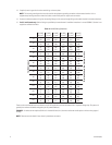
Refer to Table A for 24 VAC applications only (accessories and camera).
9. Attach the video cable to the camera. Connect power to the camera and, if applicable, to the accessories.
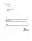
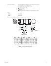
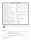
10. Attach a ground wire to the 10-32 x 3/8-inch screw on the inside of the rear plate.
NOTE:
The internal grounding terminal must be used for the equipment grounding
connection and the external terminal is for a supplementary bonding connection where local
codes or authorities permit or require such connection.
11. Push the camera sled all the way into the enclosure and fasten the sled with the 1/4-20 Allen screw.
12. Leave the desiccant bag inside the enclosure to absorb moisture. Replace the rear plate. Apply Loctite to the screws. Loctite 222 low-
strength thread locker prevents corrosion between the stainless steel screws and aluminum enclosure parts. Corrosion causes the parts to
seize, resulting in damage to them during disassembly.
GROUND
SCREW
Figure 1. Grounding Location