


Using this Quick Start Manual
Use this Quick Start Manual with your OS530/OS520
series Handheld Infrared Thermometer to set it up
and perform basic operations. These tasks are:
• Installing the Batteries
• Operating the Laser Sight
• Taking Temperature Readings
• Display Mode Sequence
For detailed information, refer to the
User’s Guide (M2891).
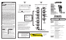
Getting Started
Parts of the Thermometer
Figure 1. Front of the Thermometer
Figure 2. Rear of the Thermometer
Laser Beam
Aperture
Identification Label
(bottom)
Tripod Thread
Mount
Analog Output Jack (1mV/deg)
ac Adapter Input Jack
RS-232 Phone Jack
(OS533, OS534,
OS523, OS524)
Thermocouple Input
Socket (SMP)
Laser
Dot/Circle
Switch
Figure 9. OS534/OS523-1 Field of View
Figure 10. OS53x-CF Field of View
Figure 11. OS523-2 Field of View
Figure 12. OS523-3 Field of View
8.7"
0.5"@ 0
5.1"
13mm @ 0
1.5"
38
130
221
0.9"
0' 16' 82'50'
*SPOT DIAMETER MEASURED
AT 90% ENERGY
D:S
=
110:1
25
0
5 15
DISTANCE: SENSOR TO OBJECT (FT)
SPOT DIA.* (MM)
SPOT DIA.* (IN)
DISTANCE: SENSOR TO OBJECT (M)
7.0"
.35"@ 24"
1.6"
9mm @ 610mm
.8"
21
42
181
.9"
22
4.0"
101
0’
3’
16’10’2’ 5’
SPOT DIA.* (MM)
*SPOT DIAMETER MEASURED
AT 90% ENERGY
5.0
0
.61
1.5
1.0
3.0
SPOT DIA.* (IN)
DISTANCE: SENSOR TO OBJECT (FT)
DISTANCE: SENSOR TO OBJECT (M)
2.9"
0.9"@ 0
1.9"
22mm @ 0
1.2"
1.0"
31
26
48
75
0.9"
0'
3'
16'10'
*SPOT DIAMETER MEASURED
AT 90% ENERGY
D:S
=
60:1
5'
5.0
0
1.0 3.01.5
SPOT DIA.* (MM)
SPOT DIA.* (IN)
DISTANCE: SENSOR TO OBJECT (FT)
DISTANCE: SENSOR TO OBJECT (M)
.45"
11.5
3"
SPOT DIA.* (MM)
*SPOT DIAMETER MEASURED
AT 90% ENERGY
7.6
SPOT DIA.* (IN)
DISTANCE: SENSOR LENS TO OBJECT (in.)
DISTANCE: SENSOR LENS TO OBJECT (cm.)
15.2
6"
9"12"
15"
.15"
.39"
.78"
1.17"
3.9
9.9
19.9
29.9
D:S = 40:1
22.9
30.5
38.1
0.9"
22
0
0
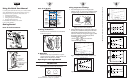
Taking Temperature Readings
1. Aim at the target. If you are not using the Laser
Sighting, use the “V” groove on top of the thermometer
to align the target to the thermometer’s field of view.
Figure 6. Field of View Positions
2. Pull and hold the trigger. To use the laser sighting, set
the laser power switch to the ON position. The Power
Indicator LED and the laser beam will turn on. The
laser beam will stay on as long as the trigger is pulled.
The target temperature and emissivity (E) will be
displayed on the LCD. You can
press the or key to increment or
decrement the target emissivity.
Figure 7. OS531, OS532, OS530L Field of View
Figure 8. OS533, OS530HR Field of View
4.8"
1.0" @ 0" to 20"
2.5cm @ 51cm
1.2"
1.0"
2.5
6.0
4.0
8.0
10.0
12.2
1601208040
1.0"
1.8"
2.4"
3.0"
3.6"
4.2"
1' 2'
200
8'6'
0**
DISTANCE: SENSOR TO OBJECT (FT)
DISTANCE: SENSOR TO OBJECT (CM)
SPOT DIA.* (IN)SPOT DIA.* (CM)
*SPOT DIAMETER MEASURED
AT 90% ENERGY
D:S = 20:1
4'
244
3' 5' 7'
20"
Field of View
Target
(ACCEPTABLE)
(UNACCEPTABLE)
START HERE
2
3
4
Parts of the Display
Figure 3. Display and Keypad View
Installing the Batteries
Invert the unit and install 4 fresh AA size batteries
as shown in Figure 4.
Figure 4. Installing the Batteries
ac Operation
The thermometer may be operated on ac power
using the optional ac adapter. 120Vac/60 Hz and
220Vac/50 Hz adapters are available.
Operating the Laser Sight Module
WARNING: DO NOT AIM THE LASER BEAM AT
ANYONE’S EYES.
The laser sight module is built into the thermometer.
Set the laser power switch to the ON position.
Figure 5. Two Laser Configurations
The thermometer is ready for operation.
2 Types of Laser Beams
Laser Dot
Laser Circle
LCK
HAL
LOBAT
ATC
LAL
PRN
°F °C
Display
Mode
Data
Associated with
Display Mode
Backlighting
Icon
Unit of
Measure
Main Display
Temperature
Locks
Trigger/
Enables
Alarms
Increments
Data/
Backlighting
ON/OFF
Display
Icons
Scrolls
through
Display
Modes
Decrements
Data/
°F to °C or
°C to °F
)
)
** Measurement distance is from the outside surface of the rubber boot.
)
)
)
)