


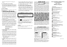

There are three display areas on the HH806 series LCD
(liquid crystal display). The Main and Second displays
are 4 _ digits with a maximum reading of 19999. These
are used for displaying the value of T1 or T2. The Third
display is for the date, time, or the differential value of
T1 to T2.
Overload: “----.-” or “OL” is display.
Battery: 1.5V x 4 PCS (SIZE AAA) UM-4 R03.
Battery Life: 120 hours typical with carbon zinc battery.
Dimensions: 160mm(H) x 83mm(W) x 38mm(D)
.
Weight: Approx. 365g including batteries.
Supplied Thermocouple:
1 meter (40”) type K insulated beaded wire thermocou-
ple
. Maximum insulation temperature is 482°C (900°F).
Thermocoupl
e accuracy is ±1.1°C or 0.4% of reading
(whichever is greater) from 0°C to 1250°C.
1. OPERATIONAL MODE
There are three operation modes-Normal, Shift, and
Setup Mode.
NORMAL MODE:
Thi
s is the default mode, the operating functions for
th
e normal mode are printed on top of each button in
white.
SHIFT MODE:
Th
e operating functions for the shift mode are printed
in gray on the buttons. While in the normal mode,
pres
s the SHIFT button to switch to shift mode. At the
lower-righ
t corner of the display, the word “Shift” is
displaye
d to indicate shift mode. To switch back to
normal mode, press the SHIFT button again.
SETUP MODE:
Pres
s the set[ ] button in normal mode to switch to
setu
p mode, the indicator “SET” is shown on the left
sid
e of the display. To switch back to normal mode,
press SET[ ] button again.
WIRELESS MODE:
Press the “ ” key for more than two seconds to start
wireles
s function. Press “
”
fo
r another two seconds
to stop wireless function. The wireless mode will shut
down if there is no wireless signal for two minutes.
SE
T CH/ID to 00,00 by pressing “T1-T2” key and
“ ” power key for more than six seconds when the
mete
r with the meter powered down. The second dis-
pla
y will show 00, which means that the channel and
ID has been set to 00.
To check the channel and ID of the meter:
Whe
n the meter is off press “ ” key and “ ” for
5 seconds. The LCD’s main display will show channel
number, the second display will show ID number.
2. NORMAL MODE
The following functions can only be used in the normal
mode.
(1) “ ”Power Button
The “ ” button turns the thermometer on or off.
When the meter is in MAX/MIN record mode, the
power off function is disabled.
(2) “[LIMITS]” Button (only Main display)
The limits function will alert the user when a meas-
urement exceeds a specified limit. To set the limit val-
ues
, refer to limits function in the setup mode. Press
the [LIMITS] button to activate the limits function; the
word “LIMIT” should be displayed on the LCD.
Whe
n the value of the main display exceeds the Hi
limit
, the word “Hi” will be displayed and the ther-
momete
r will beep in a pulsed tone. If the value of the
mai
n display is lower then the Lo limit, the word “Lo”
wil
l be displayed and the thermometer will beep in a
continuou
s tone To exit the limits function, press the
[LIMITS] button.
(3) “ ” Button
The backlight function is represented by this button
“ ”. Pressing the button will turn on or off the LCD
backlight. The backlight will turn off automatically
after.
(4) “SAVE/READ” Button
The read data function works in conjunction with the
sav
e function in the shift mode, it is used for reading
saved data. The save function can be activated in shift
mode
. Press the SAVE/READ button to read saved
data; the word “READ” should be displayed on the
LCD
. To navigate around the save data table, press the
overlay “SECOND” button until the “#” sign is dis-
playe
d on the second display. The location of the read
pointer within the saved data table will be displayed.
Th
e arrow buttons on the overlay are used for scrolling
throug
h the saved data. Press the smaller arrows “ ”
or “ ” to step through the data one at a time. Press the
larger arrows “ ” or “ ” to step through the data
te
n at a time. Pressing the overlay “ESC” button deac-
tivates the read data function.
(5) “LOG/READ” Button
The read log function works in with the
lo
g function. It is used for reading logged data. The
lo
g function can be activated in the shift mode. Press
th
e LOG/READ button to activate the log read func-
tion; the word “READ” is displayed on the LCD. Press
th
e overlay SECOND button to rotate through follow-
ing display menus: T1, T2, GRP, and #. T1 and T2:
Display
s the T1 or T2 saved data. GRP: Displays the
current group number. #: Displays the current location
of the read pointer within a selected group. The arrow
buttons on the overlay are used for scrolling through
th
e data and groups. Press the smaller arrows “ ” or
“ ” to step through the logged data or groups one at a
time. Press the larger arrows “ ” or “ ” to step
through the data or groups ten at a time. To navigate
th
e logged data and groups, press the overlay
SECON
D button until GRP appears in the second dis-
pla
y panel. Then select the group using the arrows.
Pres
s the SECOND button again until the “#” sign is
displayed. The location of the read pointer in the se-
lecte
d group will be displayed. Use the arrows to
scrol
l through the data. Pressing the overlay “ESC”
button deactivates the read data function.
(7) HOLD Mode (only Main display)
When HOLD mode is selected, the thermometer holds
th
e present readings and stops all further measure-
ments
. To activate the data hold mode, press the
HOL
D button, and “HOLD” is displayed on the LCD.
Pressin
g the HOLD button again cancels the function,
an
d the instrument will automatically resume meas-
urements.
(8) MIN/MAX with Time record Mode
(only Main display)
The MIN/MAX function records the highest and low-
es
t value recorded. It also calculates the average read-
in
g and the differences of MAX to MIN. Press
MIN/MA
X button to enter the MIN/MAX recording
mode
. The beeper emits a tone when a new minimum
or maximum measurement is recorded. Press the
MIN/MA
X button again to cycle through the current
readings
: MAX: The highest measurement recorded.
MIN
: The lowest measurement recorded. MAX-MIN:
Th
e difference of the highest and the lowest measure-
ment. AVG: The average values of the measurements.
Thi
s mode works in conjunction with the hold func-
tion
, pressing the HOLD button will stop recording
an
d measurements (Previously recorded readings are
no
t erased). Press HOLD button again to resume re-
cordin
g and measurements. To prevent accidental loss
of MIN, MAX and AVG data, the MIN/MAX function
ca
n only be cancelled by pressing and holding down
th
e MIN MAX key for more then 2 seconds. The
automati
c power-off feature, and the power, °C/°F,
REL
, SET, Hi/Lo Limits, TYPE, T1/T2 buttons are
also disabled.
(10) “T1/T2” Button (Main display)
The input selection button [T1/T2] selects the input for
the main display, T1 thermocouple or T2 thermocou-
ple
. Press the T1/T2 button to switch between the two
inputs
. When meter is turned on, it is set to the display
that was last in use.
(11) “T1/T2” Button (Second display)
The input selection button [T1/T2] selects the input for
th
e second display, T1 thermocouple or T2 thermo-
couple
. Press the T1/T2 button to switch between the
tw
o inputs. When meter is turned on, it is set to the
display that was last in use.
(12) “T1-T2/TIME” Button (Third display)
The input selection button [T1-T2] selects the system
tim
e and date, or the differential between the two
thermocouple
s (T1-T2) for the third display. Press the
T1-T
2 button to switch the display options. When
mete
r is turned on, it is set to the display that was last
in use.
3. SHIFT MODE
The following functions can only be used in the
mode.
(2) “°C/°F” Button
Press the °C/°F button to select the temperature
reading
s can be displayed in Celsius (°C) or Fahre
hei
t (°F). When the thermometer is turned on, it
to the temperature scale that was last in use.
(4) “SAVE” Button
The save function stores the T1, T2 data in a nonvola
til
e memory. Press the SAVE button to save the
ren
t data, the word SAVE is displayed to indicate
dat
a has been saved. The built in memory can store
to 128 data. The data can be read using the read
tion in the normal mode.
(5) “LOG” Button
The data log function continuously records the
accordin
g to a specified time interval. The time
va
l can be set using the interval setup function [INVT]
in the set up mode. Press the LOG button to activate
th
e log function; the indicators “LOG” and “MEM”
wil
l be displayed on the LCD. There are 16 groups
ar
e used for storing the log data, and each group
64 data slots. If the current log session exceeds 64
points
, the log function will automatically use the
grou
p to store the following data. A maximum of
dat
a points can be saved in one log session. Press
LOG button again to exit the data log function.
(6) “CLR ?” Button
The CLR function clears all the saved and logged
in memory. When the CLR button is pressed, indicator
“MEM
” is displayed and the “CLR” on upper-right
LC
D will blink. Pressing the “ENTER” button printed
on the overlay in white will clear all saved and logged
data
. Press “ESC” button to exit this function without
clearing data.
(7) “REL” Button (Main display)
The relative value function can be used for comparing
a saved reference value with other measurements.
Pres
s the “REL” button to store the current measur
men
t as the reference value, and “REL” should be
playe
d on the right part of the LCD. The next
uremen
t will display the current value compared
referenc
e value. Press “REL” button again to clear
referenc
e value and deactivate the relative value
urement function.
(8) “APO” Button
Press the APO button to turn the “Auto power
functio
n on or off. When this function is enabled,
indicato
r “APO” is shown at the upper left part
LCD
. When APO (Auto power off) is enabled, it
automaticall
y turn the thermometer off no button
presse
d for a period longer than the set time inte
(th
e default time for APO is 5 minutes). Press power
button to resume operation.
(10) “TYPE” Button (Main display)
Press this button to change the type of thermocouple
th
e main display (K/J/T/E/R/S/N). If the inputs
mai
n and second display are the same, then pressing
conjunction