


Page 11
4.7.4 When in the menu mode, the display initially shows the current value of the
parameters, such as the Setpoint of the control relay, while putting all of the outputs
on hold. The two arrow buttons are used to adjust the display value up or down.
To accept the new value press ENTER twice. While the value on the display is
being changed, the relay outputs and the analog outputs remain on hold.
The items that appear in the operation menu are:
• Password
• % Sat/ppm
• Test
• Calibration
• Temperature
• Status
• Output High
• Output Low
• Relay A Setpoint
• Relay A Deadband
• Relay B Setpoint
• Relay B Deadband
• Alarm Relay High
• Alarm Relay Low
4.8 DIP Switches
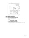
4.8.1 The controls which are frequently used in the normal operation of the instrument are
all accessible on the control panel. Some switches, which are infrequently used are
located on the back of the swing-out board.
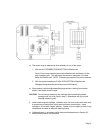
4.8.2 The DIP switches are scanned on RESET, power-up and every time the instrument
is taken into the menu mode. Therefore, after changes to the DIP switch settings,
you must take the unit offline by pressing CALL in order for the instrument to scan
the new DIP switch values.
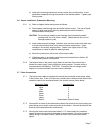
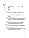
4.8.3 The following table describes the use of the 16 DIP switches:
DIP Switch
Switch Switch
Bank S1
Description of Use OFF ON
1 Selects temperature unit °F °C
2 Enables use of Password Feature YES NO
3 Fail Safe mode for Relay A NO YES
4 Direction of Control Relay A Rising Falling
5 Alarm Relay to Activate for Memory Loss YES NO
6 Fail Safe mode for Alarm Relay NO YES
7 Auto Return from menu if no button pressed NO YES
8 0-5 Vdc / 0-1 mA selector Temperature D.O.