


COMPLETING INSTALLATION
1. Insert lamp plug into junction box receptacle and secure reflector
assembly to motor frame with wing nut provided.
2. Install lamps 100 watt (maximum) for light, and 7 watt (maximum)
for night light.
3. Squeezing the grille assembly's mounting springs together, insert
springs into slots on both sides of housing.
4. Press grille assembly firmly into place against ceiling.
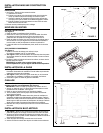
INSTALLATION IN EXISTING CONSTRUCTION
Locate fan between ceiling joists.
Plan ducting wiring before proceeding with installation. Refer to
Figure 4 for wiring and Figure 3 for ducting. CAUTION: Check
area above planned location to be sure that:
1. Ducting can be installed or that area is sufficient for proper
venting.
2. Wiring can be run to the planned location.
3. No wiring or other obstruction might interfere with installation.
INSTALLATION
1. The fan must be mounted between ceiling joists. Decide where
you want to locate the fan, and then determine where the nearest
joists are.
Locating Joists – Lightly tap the ceiling. A hollow sound means
no joist; a solid sound means a joist is present. To be sure you
have located a joist, drill a small hole (1/16") and probe into the
ceiling with a wire.
2. Locate the joists. Drill a starter hole in the ceiling between the
joists.
3. To exactly locate the edge of joist, saw a line from hole to joist.
4. Refer to page 1. Remove power/blower unit from housing.
5. Use the housing pan as a template to mark cutout: place pan
centered between joist and trace around pan.
6. Make cutout along outside of marked line.
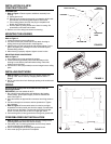
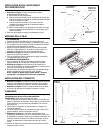
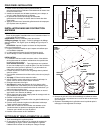
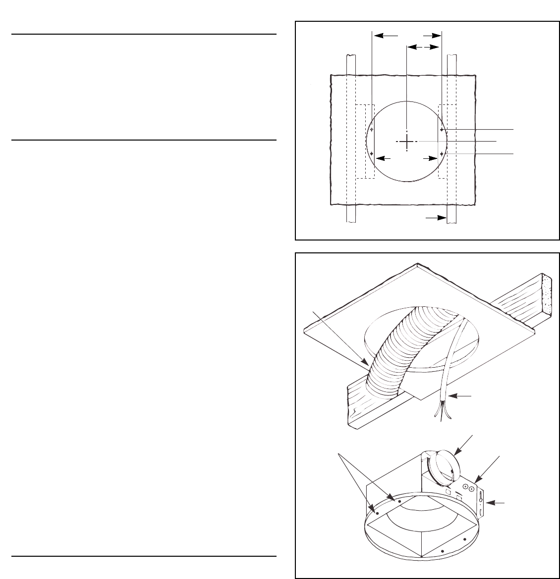
7. Refer to Figure 5. Install 2 x 4 cleats to both ceiling joists. In
some cases it may be necessary to use more than a single cleat
on one side. The distance between cleats must be at least 9
1
⁄8" but
not more than 10".
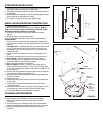
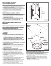
8. Remove side wiring knockout and insert and secure an approved
box connector into the wiring entrance hole.
9. Use pliers to bend both mounting tabs as flush as possible to the
side of the housing.
10. Install duct collar.
11. String wiring through box connector and connect 4" flexible duct
to duct collar.
12. Carefully push ductwork and wiring back into cutout. Place
housing into cutout.
13. Use wood screws to secure housing to cleats through four holes
in housing's pan. make sure pan is flush to finished ceiling.
14. Install Power/Blower Unit and complete installation.
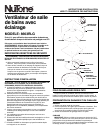
CLEANING AND RELAMPING
1. Pull grille assembly away from ceiling.
2. Squeezing the grille assembly's mounting springs together,
remove grille assembly from housing to expose socket for
relamping.
3. Clean grille and lens of assembly using a mild soap and water
solution. Assemblies with wood frames should not be immersed.
4. Replace grille assembly flat against ceiling after cleaning or
relamping.
FIGURE 5
FIGURE 6
11-1/2"
9-1/8"-10"
Joist
2"
4"
5-3/4"
➛
➛
➛
➛
4" Flexible
Duct
120vAC
House Wiring
Duct
Collar
Wiring
Knockout
Bend
Mounting
Tabs
Flush To
Side of
Housing
Mounting
Holes
➛