


© National Instruments Corporation 5 SCC-TC Series Thermocouple Input Modules User Guide
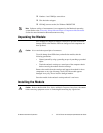
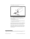
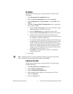
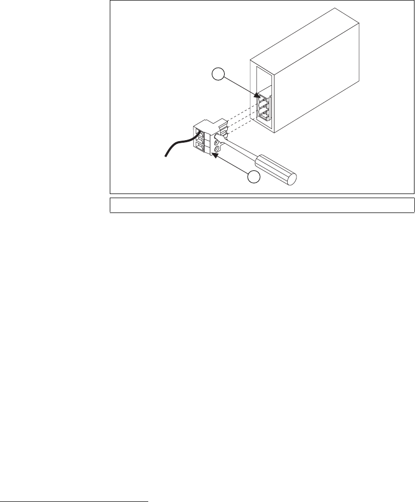
The SCC-TC02 has a fixed screw-terminal receptacle and a removable
screw-terminal block, as shown in Figure 2.
Figure 2. SCC-TC02 Two-Part Screw-Terminal System
After you install the SCC-TC02, attach the input signals to the screw
terminals of the module.
1. Remove power from the signal lines.
2. Strip 7 mm (0.28 in.) of insulation from the ends of the signal wires.
3. Insert the wires into the screw terminals.
4. Tighten the screws to 0.5 to 0.6 N ⋅ m (4.4 to 5.3 lb − in.) of torque.
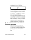
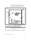
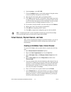
The SCC-TC02 accepts up to three signals: TC+, TC–, and GND. TC+ is
the positive thermocouple lead and TC– is the negative thermocouple lead.
1
The GND terminal connects to AIGND on the E Series DAQ device.
The SCC-TC0X has a 10 MΩ bias resistor connected from the negative
thermocouple input to ground. This resistor allows the thermocouple to be
ground-referenced or floating without requiring external bias resistors
connected to ground.
1 SCC Screw-Terminal Receptacle 2 Removable Screw-Terminal Block
1
For ANSI color-coded J-type thermocouples, the red wire is negative and the white wire is positive. Refer to the thermocouple
data sheet if possible. You can find information about other color-coding schemes in the NI KnowledgeBase at
ni.com/
support
.
3
2
1
1
2