


PRODUCT DESCRIPTION
2 – 5
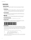
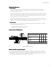
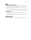
JUMPER CONFIGURATION
Master/Slave
Only drive in single drive system*
Master drive in dual drive system*
Slave drive in dual drive system
C
C
O
Cable Select
Disabled*
Enabled
O
C
Cylinder Limitation
Disabled*
Enabled
O
C
Factory Reserved O
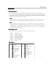
Key * = Default C = Closed (jumper installed) O = Open (no jumper)
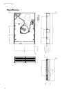
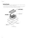
Figure 2-1
PCBA Jumper Location and Configuration
Cylinder Limitation Jumper DescriptionCylinder Limitation Jumper Description
Cylinder Limitation Jumper DescriptionCylinder Limitation Jumper Description
Cylinder Limitation Jumper Description
On some older BIOS', primarily those that auto-configure the disk drive, a hang may occur. The Cylinder
Limitation jumper reduces the capacity in the Identify Drive allowing large capacity drives to work with
older BIOS'. The capacity reported when this jumper is closed will be as follows: drives less than or equal to
32GB will report 2.1GB. Drives greater than 32GB will report 32GB.
Subsystem ConfigurationSubsystem Configuration
Subsystem ConfigurationSubsystem Configuration
Subsystem Configuration
Dual Drive SupportDual Drive Support
Dual Drive SupportDual Drive Support
Dual Drive Support
Two drives may be accessed via a common interface cable, using the same range of I/O addresses.
The drives are jumpered as device 0 or 1 (Master/Slave), and are selected by the drive select bit in the
Device/Head register of the task file.
All Task File registers are written in parallel to both drives. The interface processor on each drive decides
whether a command written to it should be executed; this depends on the type of command and which
drive is selected. Only the drive selected executes the command and activates the data bus in response to
host I/O reads; the drive not selected remains inactive.
A master/slave relationship exists between the two drives: device 0 is the master and device 1 the slave.
When the Master is closed (factory default, figure 2-1), the drive assumes the role of master; when open, the
drive acts as a slave. In single drive configurations, the Master jumper must be closed.
Cable Select OptionCable Select Option
Cable Select OptionCable Select Option
Cable Select Option
CSEL (cable select) is an optional feature per ANSI ATA specification. Drives configured in a multiple
drive system are identified by CSEL’s value:
– If CSEL is grounded, then the drive address is 0.
– If CSEL is open, then the drive address is 1.
Jumper Location / ConfigurationJumper Location / Configuration
Jumper Location / ConfigurationJumper Location / Configuration
Jumper Location / Configuration