


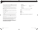
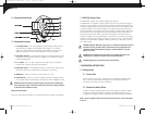
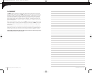

FIGURE 4
Lock Lever
Carefully, bring the two halves of the case together while positioning the wires so
they are not pinched between the two case halves. The gasket separating the
halves will be captured on the back case half.
Reinsert the three screws and tighten until the screws are snug.
(figure 3)
The device will automatically perform a calibration and begin displaying % of oxygen.
HELPFUL HINT: If unit does not function, verify that the screws are tight to allow proper
electrical connection.
HELPFUL HINT (MAXO2+ AE): Before closing the two case halves together, verify that the keyed
slot on top of the coiled cable assembly is engaged on the small tab located on the back case.
This is designed to position the assembly in the correct orientation and prevent it from rotat-
ing. Improper positioning could hinder the case halves from closing and prevent operation
when tightening the screws.
6.0 CHANGING THE OXYGEN SENSOR
6.1 MAXO
2
®
+A Model
Should the oxygen sensor require changing, the device will indicate this by
presenting “Cal Err lo” on the display after initiating a calibration.
To change the oxygen sensor, begin by removing
the three screws from the back of the device.
A #1 phillips screwdriver is required to
remove these screws.
Once the screws are removed, gently separate
the two halves of the device.
Disconnect the oxygen sensor from the printed
circuit board by pressing the un-lock lever first and
then pulling the connector out of the receptacle.
The oxygen sensor can now be replaced from the back half of the case.
HELPFUL HINT: Be sure to orient the new sensor by aligning the red arrow on the sensor with
the arrow in the back case. A small tab is located on the back case that is designed to engage
the sensor and prevent it from rotating within the case. (figure 4)
NOTE: If the oxygen sensor is installed incorrectly, the case will not come back together and
the unit may be damaged when the screws are reinstalled.
8
MANUFACTURED BY MAXTEC, INC.
9
WWW.MAXTECINC.COM
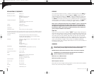
CAL Err St: O2 Sensor reading not stable
Wait for displayed oxygen reading to stabilize, when calibrating the device at
100% oxygen.
Wait for unit to reach thermal equilibrium (Please note that this can take up to
one half hour, if the device is stored in temperatures outside the specified operat-
ing temperature range).
CAL Err lo: Sensor voltage too low
Press and hold the Calibration Button for three seconds to manually force a new
calibration. If unit repeats this error more than three times, contact Customer
Service for possible sensor replacement.
CAL Err hi: Sensor voltage too high
Press and hold the Calibration Button for three seconds to manually force a new
calibration. If unit repeats this error more than three times, contact Customer
Service for possible sensor replacement.
CAL Err Bat: Battery voltage too low to recalibrate
Replace batteries
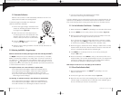
5.0 CHANGING THE BATTERIES
Should the batteries require changing, the device will indicate this in one of two ways:
• The battery icon on the bottom of the display will begin to flash. This icon
will continue to flash until the batteries are changed. The unit will continue
to function normally for approx. 200 hours.
• If the device detects a very low battery level, an error code of “E04” will be pres-
ent on the display, and the unit will not function until the batteries are changed.
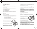
To change the batteries, begin by removing the three
screws from the back of the device. A #1 Phillips
screwdriver is required to remove these screws.
Once the screws are removed, gently separate
the two halves of the device.
The batteries can now be replaced from the back half of the
case. Be sure to orient the new batteries as indicated in
the embossed polarity on the back case.
NOTE: If the batteries are installed incorrectly the
batteries will not make contact and the device will not operate.
FIGURE 3
medicalManual.RevD.qxd 9/9/04 4:18 PM Page 14