


34
OPTIONSPROCEDURE 9
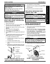
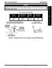
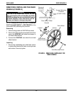
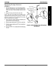
FIGURE 1 - INSTALLING THE AMPUTEE BRACKET
REAR VIEW OF
AMPUTEE BRACKET
Axle Spacer Towards OUTSIDE
of Wheelchair
RIGHT
LEFT
Axle Spacer Towards OUTSIDE
of Wheelchair
BRACKET "A"
BRACKET "B"
Locknuts
ADULT RIGHT ADULT LEFT
HEMI LEFT HEMI RIGHT
SEAT- *BRACKET AXLE SPACER SIDE OF AXLE MOUNTING
TO-FLOOR POSITION WHEELCHAIR POSITION
(on bracket) (on wheelchair)
ADULT A DOWN RIGHT TOP
ADULT B DOWN LEFT TOP
HEMI B UP RIGHT BOTTOM
HEMI A UP LEFT BOTTOM
*"A" and "B" are stamped on the sides of the amputee bracket.
This Procedure Includes the Following:
Installing the Amputee Bracket
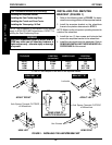
Installing the Seat Positioning Strap
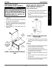
Installing the Crutch and Cane Carrier
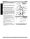
Installing the Telescoping I.V. Rod
INSTALLING THE AMPUTEE
BRACKET (FIGURE 1)
1. Refer to the following chart or FIGURE 1 to deter-
mine the mounting position of the amputee bracket:
2. Install the amputee bracket on the wheelchair
frame to the position determined in STEP 1.
NOTE: Make sure the axle spacer is pointing towards the
outside of the wheelchair.
3. Install the two (2) hex screws and locknuts that
secure the amputee bracket to the wheelchair.
4. Install the rear wheels onto the wheelchair. Refer to
REMOVING/INSTALLING THE REAR WHEELS in
PROCEDURE 9 of this manual.
O
P
T
I
O
N
S
Hex Screws
WARNING
After ANY adjustments, repair or service and BE-
FORE use, make sure all attaching hardware is
tightened securely - otherwise injury or damage
may result.
NOTE: The procedures in this section of the manual
apply to NON-RECLINER wheelchairs, EXCEPT In-
stalling the Seat Positioning Strap.