


25
FRONT CASTERS PROCEDURE 5
F
R
O
N
T
C
A
S
T
E
R
S
This Procedure Includes the Following:
Installing/Replacing Six or Eight-inch Front
Casters and Forks
Replacing/Repairing Front Caster Tire/Tube
Front Caster Mounting Adjustments
8. Test wheelchair for maneuverability.
9. Readjust locknuts if necessary, and repeat STEPS
7-8 until correct.
10. Snap dust cover over the locknut and stem.
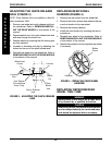
REPLACING/REPAIRING FRONT
CASTER TIRE/TUBE
WARNING
Replacement of front caster tire or tube MUST
be performed by a qualified technician.
CAUTION
As with any vehicle, the wheels and tires should
be checked periodically for cracks and wear,
and should be replaced.
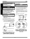
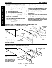
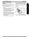
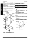
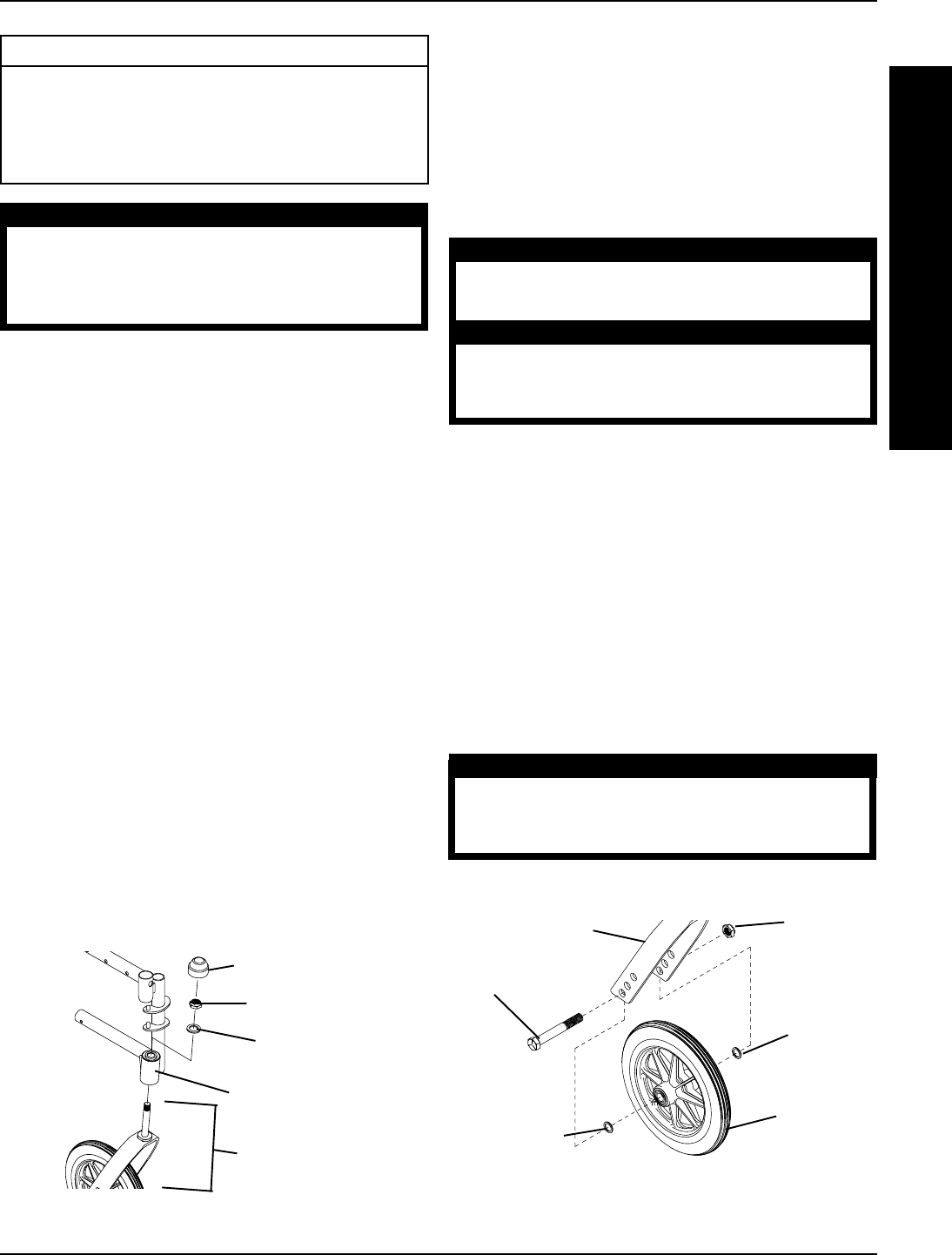
FRONT CASTER MOUNTING
ADJUSTMENTS (FIGURE 2)
1. Remove the hex screw and locknut that secures the
front caster to the fork.
2. Reposition the front caster on the fork to the deter-
mined mounting hole. Refer to CHANGING SEAT-
TO-FLOOR HEIGHT in PROCEDURE 7 of this
manual to determine front caster mounting hole for
caster size and seat-to-floor height.
3. Reinstall the spacers (6-inch caster and fork ONLY)
and securely tighten with the existing hex screw and
locknut.
WARNING
Make sure both front casters are positioned in
the same mounting hole BEFORE using the
wheelchair; otherwise injury can occur.
4. Repeat STEPS 1-3 for the opposite front caster.
FIGURE 2 - FRONT CASTER MOUNTING
ADJUSTMENTS
* Used with 6-inch Caster/Fork ONLY
*Spacer
Hex Screw
*Spacer
Front Caster
Locknut
6 or 8-inch Fork
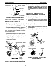
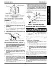
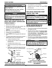
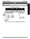
INSTALLING/REPLACING SIX OR
EIGHT-INCH FRONT CASTERS AND
FORKS (FIGURE 1)
1. Remove the dust cover.
2. Remove the locknut and nylon washer that
secures the fork to the caster headtube.
3. Drop the front caster and fork out of the caster
headtube.
4. Slide in the new front caster and fork.
5. Reassemble by reversing STEPS 1-3.
6. Repeat STEPS 1-5 for the opposite front caster and
fork .
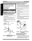
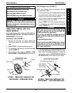
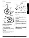
7. To properly tighten caster journal system and guard
against flutter, perform the following check:
a. Tip back of wheelchair to floor.
b. Pivot both forks and casters to top of their arc
simultaneously.
c. Let casters drop to bottom of arc.
d. Adjust locknuts according to freedom of caster
swing.
e. Repeat steps c-d untill wheels swing once to one-
side, then immediately rest in a downward position.
WARNING
After ANY adjustments, repair or service and
BEFORE use, make sure all attaching hardware
is tightened securely - otherwise injury or dam-
age may result.
FIGURE 1 - INSTALLING/REPLACING SIX OR
EIGHT-INCH FRONT CASTERS AND FORKS
Locknut
Dust Cover
Front Caster
and Fork
Nylon
Washer
Caster Headtube