


2
Ulti-Mate Air Back
NOTE: The standard attachment points are where the
eyelets are located in the upholstery.
1. If there are no eyelets, pierce a hole pattern in the
fabric, that resembles the pattern found on the neck
support bracket. Ensure the pattern is aligned with
the T-nutted holes found on the back shell.
NOTE: The cover may need to be removed to get a
more precise location of the T-nutted holes before pierc-
ing the hole pattern in the fabric.
NOTE: There is an extra set of T-nutted holes found on
the back shell for optional height adjustment. To make
these holes accessable, pierce a hole in the fabric aligned
with the T-nutted hole in the back shell. Repeat for oppo-
site hole.
NOTE: If a NEW neck support is used on an EXISTING
Curved Back than the adapter plate and support bracket
MUST be used.
NOTE: If a NEW neck support is used on a NEW Curved
Back than the support bracket can be used WITHOUT
the adapter plate.
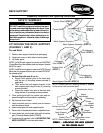
2. Secure neck adapter plate to the back shell with the
four (4) long mounting screws provided.
3. Attach neck support bracket to the adapter plate using
the two (2) short mounting screws provided.
4. Insert horizontal post into vertical post and secure
with thumbscrew.
5. If adjustment is required, refer to ADJUSTING
THE NECK SUPPORT in this instruction sheet.
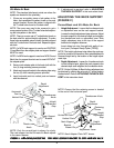
ADJUSTING THE NECK SUPPORT
(FIGURE 2)
Curved Back and Ulti-Mate Air Back
1. Height Adjustment - Loosen the thumbscrew knob
or adjustment lever on the neck support bracket.
Loosen the height adjustment stop setscrew. Adjust
the neck support to the desired height and retighten
the thumbscrew knob or adjustment lever. Slide
height adjustment stop to the top of the support
bracket and retighten setscrew.
Insert detent pin into through both walls of ver-
tical post (Transport Ready Option [TRRO]).
NOTE: The height adjustment stop allows the neck sup-
port to be removed for transfers, then reinstalled back to
the exact height set by the location of the height adjust-
ment stop.
2. Depth Adjustment - Loosen the thumbscrew knob
on the horizontal post, adjust the neck support to the
desired depth and retighten the thumbscrew knob.
NOTE: On the Ulti-Mate Air Back further adjustment can
be obtained by utilizing the extra set of T-nutted holes in
the back shell. Refer to ATTACHING THE NECK SUP-
PORT in this instruction sheet.
FIGURE 2 -AFIGURE 2 -A
FIGURE 2 -AFIGURE 2 -A
FIGURE 2 -A
TTTT
TTTT
TT
AA
AA
A
CHING/ADJUSTING CHING/ADJUSTING
CHING/ADJUSTING CHING/ADJUSTING
CHING/ADJUSTING
THE NECK SUPPORTHE NECK SUPPOR
THE NECK SUPPORTHE NECK SUPPOR
THE NECK SUPPOR
T BRAT BRA
T BRAT BRA
T BRA
CKET CKET
CKET CKET
CKET
TO ULTO UL
TO ULTO UL
TO UL
TI-MATI-MA
TI-MATI-MA
TI-MA
TE TE
TE TE
TE
AIR BAIR B
AIR BAIR B
AIR B
AA
AA
A
CKCK
CKCK
CK
NOTE: Only the curved back is shown for clarity.
The neck support on the Ulti-mate Air Back adjusts
in the same manner.
Neck Support
Bracket
Thumbscrew
Knob
Thumbscrew
Knob
Height
Adjustment
Stop
Vertical Post
Thumbscrew Knob
Neck Support
Bracket
Height
Adjustment
Stop
Vertical Post
NOTE: Neck Adapter Plate NOT shown.
Horizontal Post
Adjustment Lever
Detent Pin
Height
Adjustment
Depth
Adjustment
NOTE: Ensure that the retaining screw is located
in the end of the horizontal post.
Retaining
Screw
Horizontal
Post
Depth
Adjustment