


PERSONAL
BACK
SECTION
A
A
5
6
4
2
1
3
Personal
Back
(Inside)
Groove
for 3/16"
Retaining
Ring
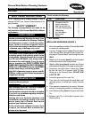
FIGURE 1 - INSTALLING HARDWARE
Mounting
Holes
Latch Pin
Handle
Nylon Locking Key
"Teardrop" end of Nylon Lock-
ing Keys MUST be installed at
a 30
O
angle to the handles of
the Latch Pins.
Personal Back
(Inside)
Handle
Apply LOCTITE to
Threads of Latch Pin
NOTE: The teardrop end of the locking key MUST be
installed at a 30
O
angle to the Left and Right handles of
the Latch Pins or they will NOT properly attach to the
brackets on the wheelchair.
CAUTION
When using LOCTITE 290, follow the manufac-
turers' recommendations.
1. Remove Nylon Locking Key from the Latch Pin
2. Place a small bead of LOCTITE 290 onto the
threads of the Latch Pin.
3. Install the Nylon Locking Key onto the threads of the
Latch Pin at a 30
O
angle to the handle.
4. Proceed to install the remaining Nylon Locking Key
onto the Latch Pin of the other side.
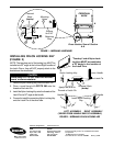
INSTALLING NYLON LOCKING KEY
(FIGURE 2)
LEFT ASSEMBLY RIGHT ASSEMBLY
FIGURE 2 - INSTALLING NYLON LOCKING KEY
30
O
30
O
Install Nylon Locking
Key
Handle
(VIEWED FROM HANDLE END OF ASSEMBLY.)
Cross Section View of Section
A-A
Invacare Corporation www.invacare.com
USA Canada
One Invacare Way 5970 Chedworth Way Invacare and "Yes, you can" are trademarks of Invacare
Elyria, Ohio USA Mississauga, Ontario Corporation.
44036-2125 L5R 3T9, Canada © 2000 Invacare Corporation
800-333-6900 905-890-8838 Form No. 96-122 Part No. 1060985 Rev A (1) 6/00