1
SAFETY SUMMARY
WARNING
DO NOT install this equipment without first read-
ing and understanding this instruction sheet. If you
are unable to understand these instructions, con-
tact a healthcare professional, dealer or techni-
cal personnel if applicable before attempting
to install this equipment - otherwise, injury or dam-
age may occur.
Ensure that the seat is fixed to the wheelchair. A
loose seat may lead to potentially dangerous
situations with positioning devices.
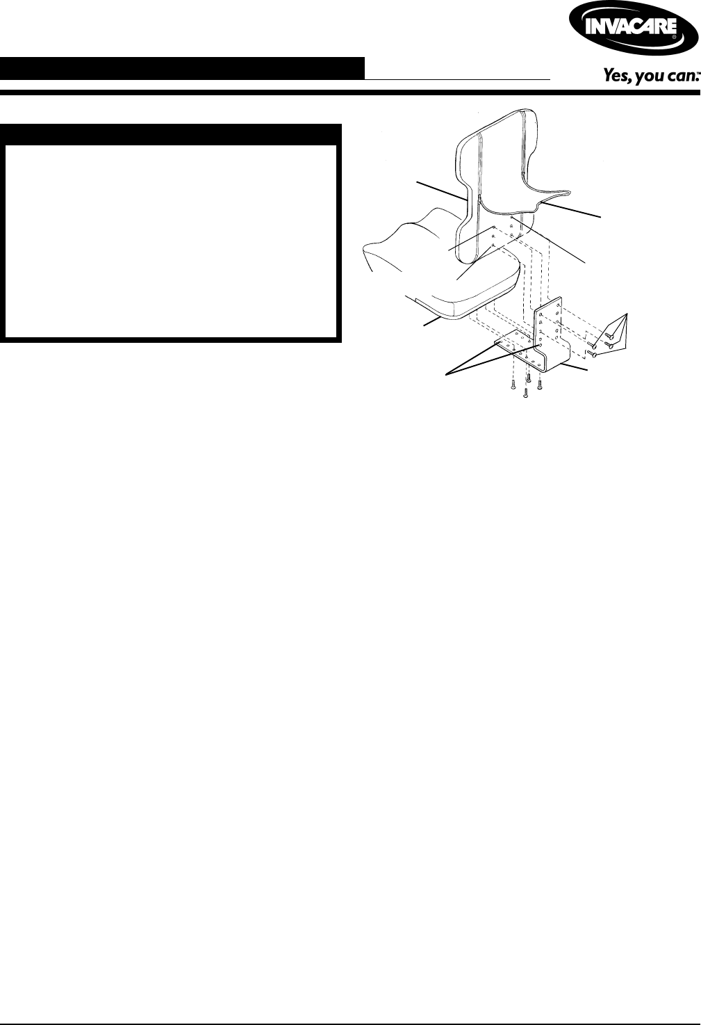
FIGURE 1 - ATTACHING/ADJUSTING THE
FIXED GROWTH BRACKET
Top Set
Bottom Set
Growth Bracket
Adjustment
holes
Ulti-Mate
Base
Six (6) T-nutted
mounting holes
Center Panel
Curved
Back
Mounting
Screws
ATTACHING/ADJUSTING THE
FIXED GROWTH BRACKET
Attaching the Growth Bracket
NOTE: The growth bracket attaches to the Child/Junior
Size Curved Back only.
1. Remove the growth bracket and attaching hardware
from packaging.
2. Unzip center panel of the back cover, exposing the
six (6) T-nutted mounting holes.
NOTE: Make sure the growth bracket is positioned cor-
rectly. The flat portion of the growth bracket provides
depth adjustment for the Ulti-Mate Base. The angled
portion of the growth bracket provides height adjustment
for the Curved Back. See FIGURE 1.
3. Install four (4) of the mounting screws through the
holes in the growth bracket and into the back shell.
Securely tighten.
NOTE: On the curved back, the standard attachment
points are the top and bottom sets of holes. Refer to the
FIGURE 2-ATTACHMENT POINTS in this instruction
sheet for optional attachment points.
4. Install four (4) of the mounting screws through the
holes in the growth bracket and into the underside of
the Ulti-Mate Base. Securely tighten.
NOTE: On the Ulti-Mate Base, the standard attachment
points are the front and back sets of holes. Refer to the
FIGURE 2-ATTACHMENT POINTS in this instruction
sheet for optional attachment points.
5. If adjustment is required, refer to ADJUSTING THE
GROWTH BRACKET in this instruction sheet.
Adjusting the Growth Bracket
(FIGURE 1)
ADJUSTING THE BACK HEIGHT.
1. If necessary, unzip center panel of the back cover.
2. Remove the four (4) mounting screws that secure
the growth bracket to the back.
3. Adjust the back up or down until the desired mount-
ing position is obtained.
4. Reinstall the four (4) mounting screws through the
growth bracket and into the back shell. Securely
tighten. Refer to the FIGURE 2- ATTACHMENT
POINTS
in this instruction sheet for standard and
optional attachment points.
5. Zip center panel of back cover closed.
ADJUSTING THE ULTI-MATE BASE
DEPTH.
1. Remove the four (4) mounting screws that secure
the growth bracket to the Ulti-Mate Base.
2. Adjust the seat forward or back until the desired
mounting position is obtained.
3. Reinstall the four (4) mounting screws through the
growth bracket and into the seat. Securely tighten.
Refer to the FIGURE 2 - ATTACHMENT POINTS In
this instruction sheet for standard and optional at-
tachment points.
Growth Bracket
Assembly, Installation and Operating Instructions


