


899 Cleveland Street
P.O. Box 4028
Elyria, Ohio 44036-2125
Phone 1-(800)-333-6900
Form No. 95-166 Part No. 1060540 Printed in U.S.A.
ASSEMBLY OF THE EXISTING PUMP, NEW
BOOM AND SWIVEL BAR ASSEMBLIES
Pump Assembly
1. Using the nut and bolt provided, assemble the
pump to the new boom. Refer to FIGURE 2.
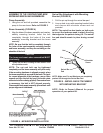
Boom Assembly (FIGURE 4)
CAUTION
The boom and mast when assembled MUST
pivot easily.
2. Tighten the bolt and nut using an Allen wrench and
an adjustable wrench.
NOTE: The nut and bolt can be tightened
completely and the boom assembly will pivot easily
if the mounting hardware is aligned properly when
the boom assembly is secured to the mast. To check
for correct alignment of the hardware, use an Allen
wrench and turn the bolt by hand (it should rotate
without a lot of force being applied). If excessive force
is necessary, the bolt is NOT aligned properly.
Disassemble and repeat assembly procedures until
proper alignment is obtained.
1. Align the holes of the boom assembly and mast as-
sembly mounting bracket. Insert the bolt
completely through the holes of the mast
assembly mounting bracket and the boom
assembly.
NOTE: Be sure that the bolt is completely through
the holes of the mast assembly mounting bracket
and boom assembly; and they are not riding on the
shoulder of the bolt.
FIGURE 4 - NEW BOOM INSTALLATION
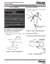
FIGURE 5 - SWIVEL BAR ATTACHMENT
WITH MOUNTING BRACKET
Swivel Bar
Pad
Pin
NOTE: Make sure Pin and Washers are completely
pushed UP through the Swivel Bar Pad.
1. Pull the pin up through the swivel bar pad.
2. Line-up hole in pin with mounting bracket holes
and secure with shoulder screw and nut
provided.
NOTE: The swivel bar has hooks on both ends
to accept the hardware used to attach the sling
that supports the patient during lift. The swivel
bar pad should remain in place during normal
use.
Swivel Bar Attachment with Mounting
Bracket (FIGURE 5)
NOTE: Refer to Owner's Manual for proper
operation of your patient lift.
Shoulder
Screw
Nut