SECTION 8—ANTI-TIPPERS/WHEEL LOCKS
Part No. 1076155 83 9000 Series
2. Dependingonthemodelofwheellockinstalledonthewheelchair,performone(1)of
thefollowing:
•Push‐to‐Lock‐Toengage, pushthewheellockhandleforward.
•Pull‐to‐Lock‐Toengage,pullthewheellockhandlebackward.
3. DisengagethewheellocksbyreversingSTEP2.
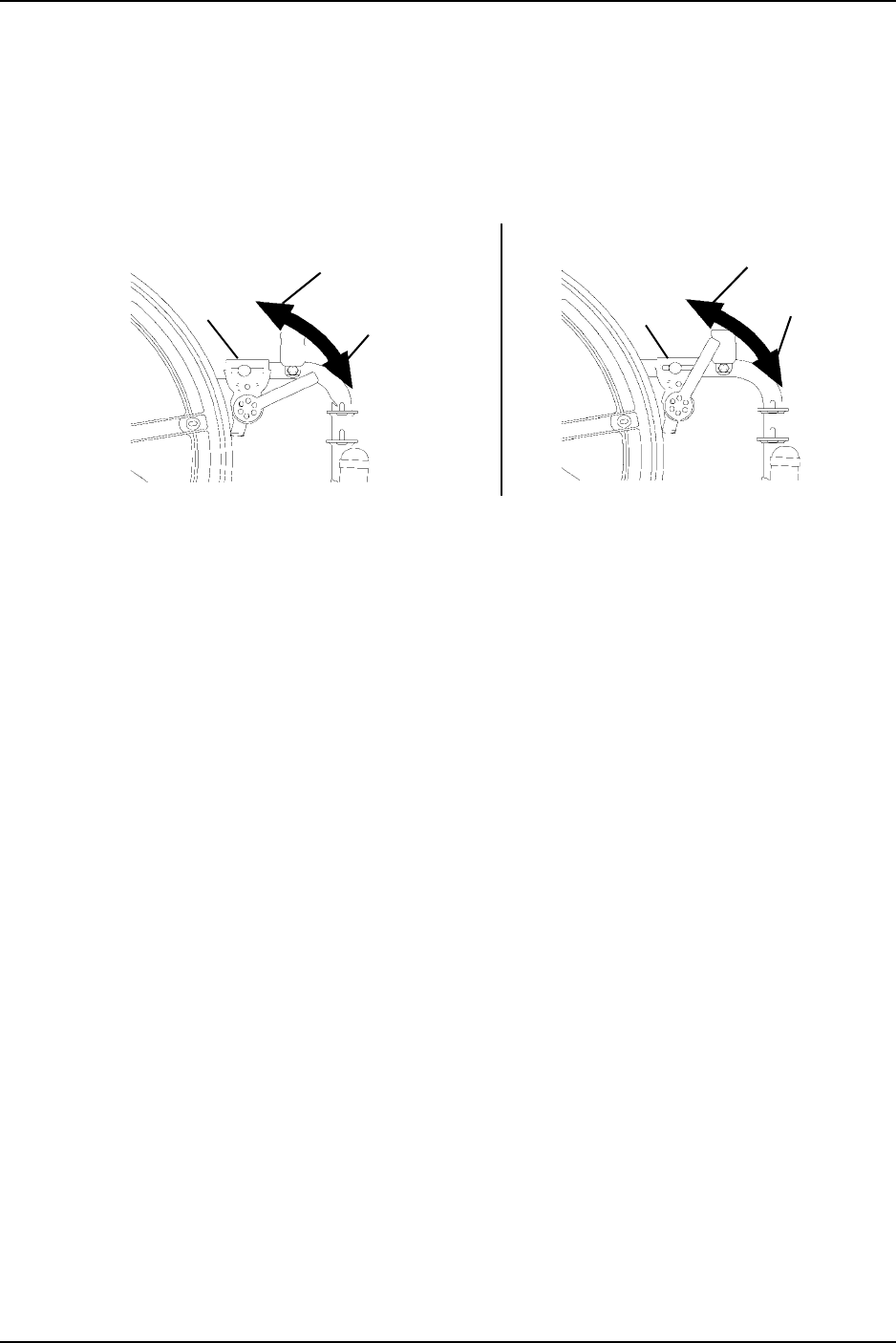
FIGURE 8.3 Using Patient Operated Disk Wheel Locks
Adjusting Patient-Operated Wheel Locks
NOTE:Forthisprocedure,refertoFIGURE 8.4.
NOTE:Thepush‐or‐pull‐to‐lockwheellocksarealsoanoptiononthe9000XTRecliner.
NOTE:Ifwheelsarepneumatic,beforeadjustingorreplacingthewheellockassemblies,ensure
thatthetiresareinflatedtotherecommendedpsionthesidewalloftire.Therecommendedtire
pressureislocatedonthesidewallofthetire.
1. Disengagethewheellocks.
2. Performone(1)ofthefollowing:
•Bolt‐onWheellocks‐Loosentheboltandlocknutthatsecurethewheellocktothe
wheelchairframe.
•Clamp‐onwheellocks‐Loosenthetwo(2)socketscrewsthatsecurethewheellock
tothewheelchairframe.
3. Repositionthewheellocksothatwhenengaged,thewheellockshoeembedsthetire
1/8‐inch(3/16‐inchforpneumatictires)andholdstheoccupiedwheelchairinplace
whenpushed.
4. Securelytightentheboltandlocknutorsocketscrewssecuringthewheel
locktothe
wheelchairframe.
5. Engagethewheellock.
6. Measurethedistancethewheellockisembeddedintothetireasshownin
FIGURE 8.4.
NOTE:Anywheellockadjustmentshouldembedthewheellockshoeatleast1/8‐inch(3/16‐inch
ifpneumatictire)intothetirewhenengaged.
Wheel
Lock
Wheel
Lock
Push-To-Lock Pull-To-Lock
Unlocked
Position
Unlocked
Position
Locked
Position
Locked
Position


