


3
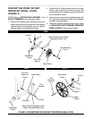
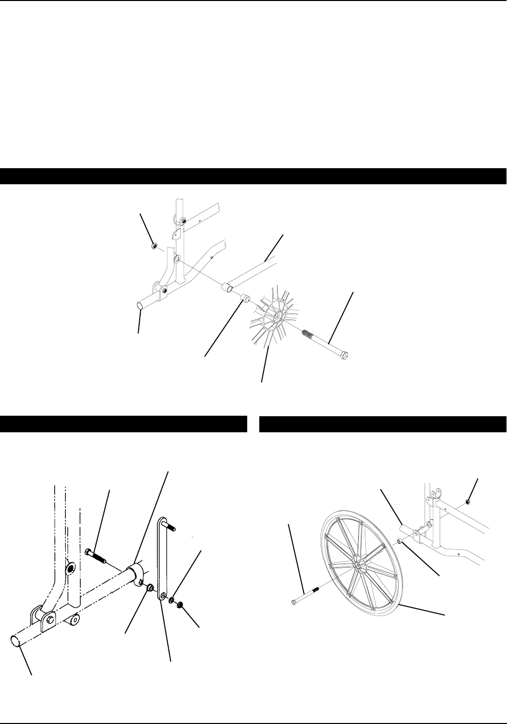
CONVERTING FROM PATIENT
OPERATED WHEEL LOCKS
(FIGURE 4)
NOTE: Refer to INSTALLATION WARNING in the
SAFETY SUMMARY in this instruction sheet.
1. Remove the existing axle mounting screw and
locknut that secures the rear portion of the patient
operated wheel lock assembly, pivot arm spacer
and rear wheel to the wheelchair frame.
Axle Mounting
Screw
Rear Portion of the Patient
Operated Wheel Lock
5/16-inch
Mounting
Screw
Bushing
Tube Clamp
Thin
Washer
Strap and Stud Assembly of the
Patient Operated Wheel Lock
Locknut
Locknut
Wheelchair
Frame
Rear
Wheel
Axle
Mounting
Screw
Spacer
FIGURE 4 - CONVERTING FROM PATIENT OPERATED WHEEL LOCKS
Locknut
Pivot Arm
Spacer
Rear Wheel
STEP 1
STEP 2
STEP 3
Wheelchair
Frame
Wheelchair
Frame
2. Remove the 5/16-inch mounting screw, bushing,
washer, and locknut that secures the strap and
stud assmebly of the patient operated wheel lock
to the wheelchair frame.
3. Secure the rear wheel to the wheelchair frame with
the axle mounting screw and the 3/4-inch spacer
provided. Securely tighten.
4. Install the attendant operated wheel locks. Refer
to REPLACING THE ATTENDANT OPERATED
WHEEL LOCKS in this instruction sheet.