


2
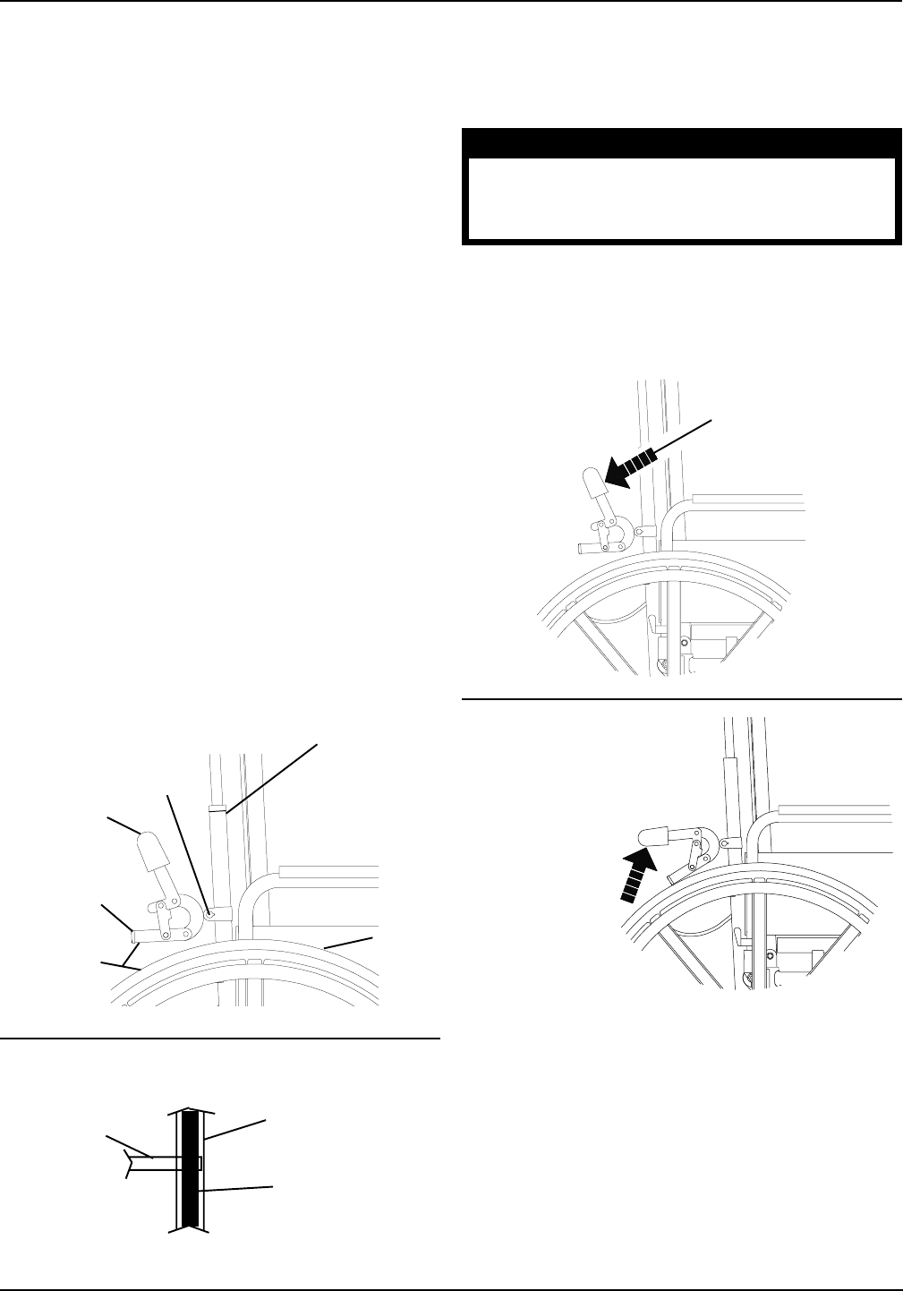
Wheel Lock
(STEP 1)
Wheel
Lock Shoe
(STEP 2)
5/32 to
5/16- inches
(STEP 2)
Locknut
(STEP 1)
Rear
Wheel
Recliner
Tube
(STEP 1)
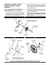
FIGURE 2 - ADJUSTING THE ATTENDANT
OPERATED WHEEL LOCKS
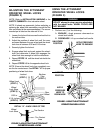
Tire Section
Tire Contact
Area
DETAIL "A" - BACK VIEW OF TIRE
Wheel
Lock Shoe
ADJUSTING THE ATTENDANT
OPERATED WHEEL LOCKS
(FIGURE 2)
NOTE: Refer to INSTALLATION WARNING in the
SAFETY SUMMARY in this instruction sheet.
NOTE: If wheels are pneumatic, before adjusting or
replacing the wheel lock assemblies, ensure that the
tires are inflated to the recommended psi. The recom-
mended psi is listed on the side wall of tire.
1. Loosen the locknut that secures the wheel lock to
the recliner tube.
2. Adjust the position of wheel lock until the mea-
surement between the rear wheel and the wheel
lock shoe is between 5/32 and 5/16-inches.
3. Securely tighten the locknut.
4. Engage wheel lock and push against the wheel-
chair and determine if wheel lock engages the
wheel lock shoe enough to hold the wheelchair.
5. Repeat STEPS 1-4 until the wheel lock holds the
wheelchair.
6. Repeat STEPS 1-5 for the opposite wheel lock.
NOTE: Ensure the wheel lock shoe completely cov-
ers the tire contact area. See DETAIL "A" for proper
positioning of wheel lock shoe.
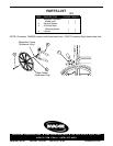
APPLY
PRESSURE
HERE TO
DISENGAGE
LOCKED
POSITION
APPLY PRESSURE
HERE TO ENGAGE
UNLOCKED
POSITION
FIGURE 3 - USING THE ATTENDANT
OPERATED WHEEL LOCKS
USING THE ATTENDANT
OPERATED WHEEL LOCKS
(FIGURE 3)
WARNING
DO NOT attempt to stop a moving wheelchair
with the wheel locks. WHEEL LOCKS ARE
NOT BRAKES.
1. Perform one (1) of the following:
A. ENGAGE - Apply pressure downward on
wheel lock handle.
B. DISENGAGE - Lift up on wheel lock handle.