


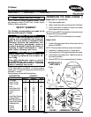

I.V. Hanger
Upper
I.V. Tube
Adjusting Knob
Lower I.V. Tube
Black Plastic
Insert
Base
Large steel washer
Small Steel
Washer
Lock Washer
Bolt
ASSEMBLING THE I.V. STAND
(FIGURE 2)
1. Perform one (1) of the following:
A. MODELS 6681-5 AND 6845-5 -
1. Place black plastic insert into the hole pro-
vided on top of the base.
2. Insert the lower I.V. tube through the black plas-
tic insert and the base.
3. Secure the lower I.V. tube to the base with the
large steel washer, small steel washer, lock
washer and bolt. Securely tighten.
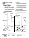
FIGURE 2 - ASSEMBLING THE I.V. STAND
Invacare Corporation www.invacare.com
USA Canada
One Invacare Way 5970 Chedworth Way Invacare and "Yes, you can" are trademarks of Invacare
Elyria, Ohio USA Mississauga, Ontario Corporation.
44036-2125 L5R 3T9, Canada © 2000 Invacare Corporation
800-333-6900 905-890-8838 Form No. 96-140 Part No. 1063112 Rev A (1) 8/2000
B. MODEL 6845 -
1. Align the upper base half and the lower base
half as shown in FIGURE 2.
NOTE: The lower base half has a recess.
2. Insert the bolt UP through wrench, small steel
washer, mounting holes in lower base half and
upper base half and large steel washer.
3. Secure the lower I.V. tube to the base with the
bolt. Tighten securely.
2. Place I.V. hanger onto the threaded end of the upper
I.V. tube. Turn clockwise to tighten.
NOTE: Ensure the I.V. hanger is screwed tightly onto the
upper I.V. tube.
3. Insert upper I.V. tube into the lower I.V. tube.
4. Insert adjusting knob into the mounting hole on the
lower I.V. tube.
5. Raise the upper I.V. tube to the desired I.V. stand height.
6. Tighten adjusting knob, by turning clockwise, at de-
sired I.V. stand height.
I.V. Hanger
Upper
I.V. Tube
Adjusting Knob
Lower I.V. Tube
Upper
Base Half
Bolt
Lower
Base Half
MODELS 6681-5 AND 6845-5
MODEL 6845
Threaded
End
Threaded
End
Wrench
Small Steel Washer
Large Steel Washer