


Invacare Corporation www.invacare.com
USA Canada
One Invacare Way 5970 Chedworth Way Invacare
®
and "Yes, you can" are trademarks of Invacare
Elyria, Ohio USA Mississauga, Ontario Corporation.
44036-2125 L5R 3T9, Canada © 2001 Invacare Corporation
800-333-6900 905-890-8838 Form No. 98-146 Part No. 1076198 Rev C (1) 1/01
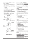
Removing/Installing The Stingray Brake
Pad (FIGURE 11)
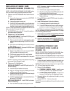
1. Remove the tire. Perform the following as shown in
DETAIL “A” of FIGURE 11:
A. Remove the cap covers from both sides of the tire.
B. Remove the screw and locknut that secure the tire
to the rollator forks.
C. Remove the tire.
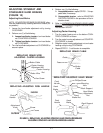
2. Loosen the set screw securing the brake cable to the
EXISTING brake pad assembly.
3. Remove the mounting screw and locknut that secures
the EXISTING brake pad assembly to the rollator. Set
mounting screw aside.
NOTE: It may be necessary to straighten the end of the
brake wire to pull it through the brake pad assembly.
NOTE: Note the position and orientation of the EXIST-
ING brake pad assembly prior to removing.
4. Pull the EXISTING brake pad assembly away from
the rollator forks and discard.
5. Position the NEW brake pad assembly between the
rollator forks and secure with the EXISTING mounting
screw and locknut as shown in FIGURE 11. Securely
tighten.
NOTE: The new set screw is shipped installed as part of
the new brake pad assembly.
6. Insert brake wire through the new brake pad assem-
bly and securely tighten the set screw.
7. Reverse STEP 1 to reinstall the tire.
8. Test brake, if necessary adjust brake.
9. If necessary, repeat STEPS 1-9 on remaining brake.
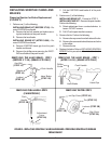
FIGURE 11 - REMOVING/INSTALLING THE
STINGRAY BRAKE PAD
Cap
Cover
Screw
Locknut
Cap
Cover
Tire
Brake Pad Assembly
Mounting Screw
Rollator
Forks
Brake Cable
Set Screw
Locknut
DETAIL “A”