SECTION 4—INSPECTION AND COMPRESSOR INTERFACE
HomeFill
™
14 Part No 1148114
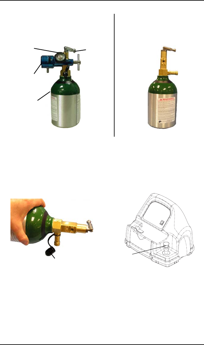
FIGURE 4.2 Component Identification
4. Remove the post valve cover (located on the cylinder) and
the connector fillport covers (located on the compressor)
(FIGURE 4.3).
FIGURE 4.3 Fillport Covers
5. On the compressor unit, momentarily push DOWN on the
outer ring (sleeve) of the connector fillport to reset the
connector (FIGURE 4.4).
Conserver/
Regulator
Cylinder
Toggle
Valve
Gauge
CONSERVER/REGULATOR
INSTALLED
CONSERVER/REGULATOR
REMOVED
Connector
Fillport Cover
Post Valve Cover


