Part No 1086188 3 Anti-tippers
8. Measurethedistancebetweenthebottomoftheanti‐tipperwheelsandthe
ground/floor.
•Non‐AdjustableHeightAnti‐TipperAssemblies:Ifthedistancebetweenthebottomof
theanti‐tipperwheelsandtheground/floorisnot1½to2‐inches,callInvacare
TechnicalSupportatthenumberlistedonthebackpage.
•AdjustableHeightAnti‐TipperAssemblies:Ifthedistancebetweenthebottomof
anti‐tipperwheelsandtheground/floorisnot1½to2‐inches,adjustanti‐tippers.Refer
toAdjustingAnti‐Tippersonpage 3.
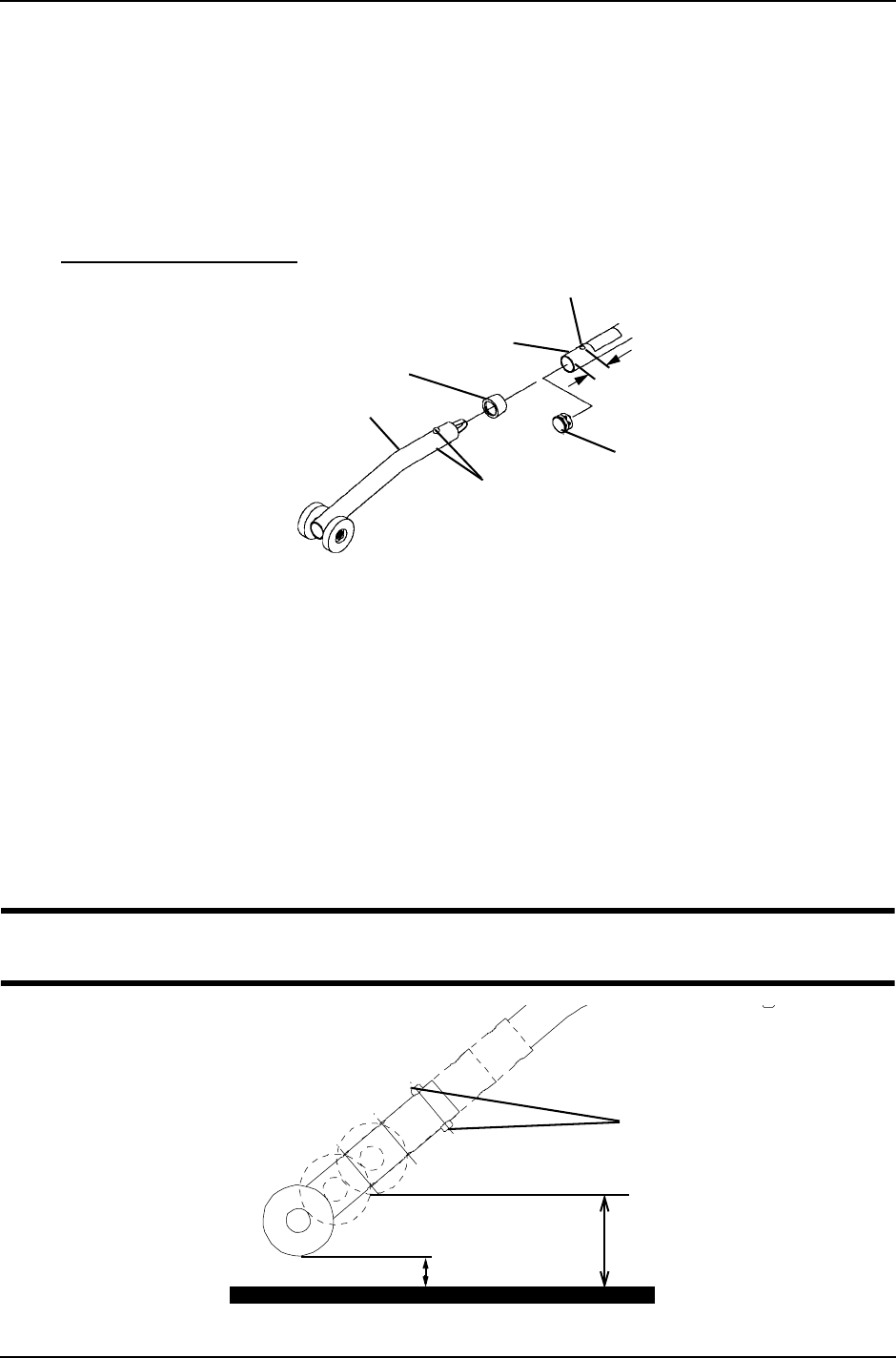
FIGURE 1 Installing Anti-Tippers
Adjusting Anti-Tippers
NOTE:Forthisprocedure,refertoFIGURE 2.
NOTE:A1½to2‐inchclearancebetweenthebottomoftheanti‐tipperwheelsandtheground/floor
MUSTbemaintainedatalltimes.
1. Pressthereleasebuttonsnearthewheeledportionoftheanti‐tipperandslidethe
anti‐tipperupordowntoachievethe1½to2‐inchclearance.
2. Checktomakesurethatthereleasebuttonsare fullyengagedintheadjustmentholes.
ƽ WARNING
WARNINGEnsure both anti-tippers are adjusted to the same height.
FIGURE 2 Adjusting Anti-Tippers
*NOTE:Non‐adjustable
anti‐tippershown.
15/16-inch
(STEP 3)
Plug Button or End
Cap (End cap not
shown) (STEP 1)
Spring Button(s)
(STEP 5)
*Anti-Tipper
Anti-Rattle
(if provided)
(STEP 4)
Locking Hole (9/32-inch Diameter)
(STEPS 2,3)
Lower
Frame
Tube
1½ inches
Release Buttons
2 inches


