TP970 AND TP9600 SERIES PNEUMATIC THERMOSTATS
9
75-7134—1
15
14
13
12
11
10
9
8
7
6
5
4
3
2
1
(100)
(90)
(80)
(70)
(60)
(50)
(40)
(30)
(20)
(10)
0
15
12.5 10 7.5 5 2.5 1512.5107.552.5
SETPOINT
SETPOINT
(8) (7) (6) (5) (4) (3) (2) (1) (8)(7)(6)(5)(4)(3)(2)(1)
BRANCHLINE PRESSURE—PSI (kPa)
DEVIATION IN SPACE TEMPERATURE—DEGREES F (C)
BELOW SETPOINT
ABOVE SETPOINT
C3537
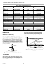
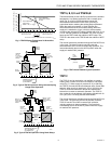
TP970D MINIMUM
THROTTLING RANGE =
5F (2.8C)
TP970D MAXIMUM
THROTTLING
RANGE = 20F (11.1C)
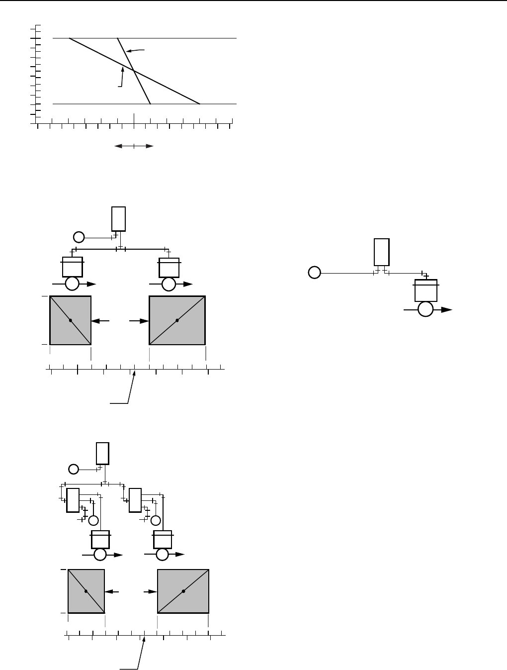
Fig. 3. TP970D Space Temperature Vs Branchline
Pressure.
VALVE
OPEN
VALVE
CLOSED
4 DEGREES F
(2.2 DEGREES C)
ZERO
ENERGY
BAND
THERMOSTAT SETTING
TR=10 DEGREES F
(5.6 DEGREES C)
20C
22C
24C
66F 68F 70F 72F 74F 76F 78F
TP970C
DIRECT
ACTING
COOLING
VALVE
9 TO 13 PSI
(62 TO 90 kPa)
SPRING
HEATING
VALVE
2 TO 5 PSI
(14 TO 34 kPa)
SPRING
N.C.
N.O.
M B
M
C3538
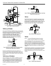
Fig. 4. Typical TP970C Operation Using Selected Spring
Range Valve Operators.
TP970C
DIRECT
ACTING
HEATING
VALVE
3 TO 10 PSI
(21 TO 68.9 kPa)
COOLING
VALVE
3 TO 10 PSI
(21 TO 68.9 kPa)
RP971A—3 PSI
RANGE—SET
10 PSI (68.9 kPa)
START
RP971A—3 PSI
SPAN—SET
3.9 PSI (26.9 kPa)
START
M
M
M B
2
1
4
3
EXH
N.O.
M
2
1
4
3
EXH
N.C.
C3539
VALVE
OPEN
VALVE
CLOSED
20C
22C
24C
66F 68F 70F 72F 74F 76F 78F
4 DEGREES F
(2.2 DEGREES C)
ZERO
ENERGY
BAND
THERMOSTAT SETTING
TR=10 DEGREES F
(5.6 DEGREES C)
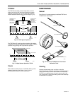
Fig. 5. Typical TP970C Operation Using Ratio Relays.
TP971A, B, D, E and TP9610A,B
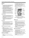
These thermostats provide a BLP proportional to the ambient
temperature. In a heating application with a normally open
valve (Fig. 6), a fall in room temperature causes the
thermostat to lower the BLP to the valve, providing a
proportional action matching the existing load requirement.
When the supply air pressure is 13 psi (90 kPa), the
thermostat controls at the normal DAY setting. When the
supply air is switched to 18 psi (124 kPa), the thermostat
controls at the reduced NITE setting. Models with 16 or 21 psi
(110 or 145 kPa) pressure are available. The TP971D is the
same as the TP971A with the addition of NITE setup. The
TP971E is the same as the TP971B with the addition of NITE
setup.
The manual reset lever protrudes through the DAY/AUTO slot
in the cover. The lever is used to manually reset the
thermostat from AUTO to DAY to restore day operation. The
lever automatically returns to the AUTO position when the
supply air reaches DAY pressure.
TP971A OR
TP9610A
DAY
13 PSI
(90 kPa)
NITE
18 PSI
(124 kPa)
M B
N.O.
M
HOT WATER
OR STEAM
SUPPLY
C3540-1
Fig. 6. TP971A and TP9610A Typical Operation.
TP971C
The TP971C can be used with a unit ventilator to control a
heating valve, outdoor- and return-air dampers, and blower
motor (Fig. 7). When supply air pressure is 13 psi (90 kPa),
the TP971C controls the valve and damper at the normal DAY
setpoint. When supply air pressure is 18 psi (125 kPa), the
TP971C closes the outdoor-air damper and switches the
blower from constant to automatic operation. The TP971C
then cycles the unit at reduced night setpoint. Models with 18
or 21 psi (125 or 145 kPa) pressure are available.
The manual reset lever protrudes through the DAY/AUTO slot
in the cover. The lever may be used to manually reset the
TP971C from AUTO to DAY to restore DAY operation,
including outdoor-air damper operation. The reset lever
automatically returns to the AUTO position when the supply
air reaches DAY pressure.


