20
TP970 AND TP9600 SERIES PNEUMATIC THERMOSTATS
75-7134—1
TP978E
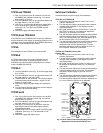
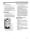
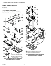
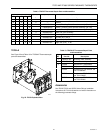
See Figure 24 and Table 9 for TP978E Thermostat repair
parts and assemblies. The TP978A-D Thermostats have not
been replaced.
5
4
3
2
1
M12207
Fig. 24. TP978E Exploded View.
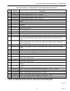
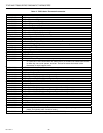
Key
No. Part No. Description
10 14002051-001 Pneumatic Assembly, TP970-TP973 - Includes 10B and 10C below
14002102-004 Pneumatic Assembly, TP974A - Includes 10B and 10C below
10A — Tab and Screw - TP974A
10B 14004419-001 Gasket, Restrictor block (included with 14002374-XXX)
10C 14001865-001 Filter
10D 14002374-001 Restrictor Block Assembly (0.005 restrictor, 2 pipe) - TP970A-D; TP971A, B, D, E; TP972A;
TP973A, B
14002374-005 Restrictor Block Assembly (0.005 restrictor, 3 pipe) - TP971C
14002374-006 Restrictor Block Assembly (0.007 restrictor, 2 pipe) - TP974A
10E 14002373-001 Switchover Spring Assembly, silver - 16 to 21 psi (110 to 145 kPa)
14002373-002 Switchover Spring Assembly, gold - 13 to 18 psi (90 to 124 kPa)
14003923-001 Switchover Spring Assembly, blue - 20 to 25 psi (140 to 175 kPa)
10F 14002372-001 DAY/AUTO Lever Assembly
11 — Screw, No. 4-40 x 5/8 an head (included with 14002374-XXX)
12 14002053-001 Wall Plate Assembly with setscrews 14003454-001 (2)
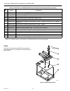
*Replace the Setpoint Cam Assembly and Nozzle, Throttling Plate, Bimetal Assembly together.
†If there is no antihum spring or cone, there is an adhesive paper dot on the throttling plate.
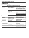
Table 8. TP970-TP974 and TP9600-TP9630 Thermostat Repair Parts and Assemblies (continued).


