


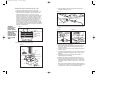

Minimum Water Level
Flow Control Valve
(+) faster water
output
(-) slower water
output
Attention:
In order to get
best results,
please operate
pump completely
submerged.
Keep the water
level above the
minimum water
level ALL THE
TIME.
Figure 1
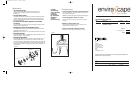
Figure 4
Connector
Tube
4. Insert the waterproof light into the light hole located on the
underside of the panel. (Fig. 3)
5. Join the pump outlet and the connector tube under the panel.
(Fig. 4)
6. Place the panel on top of the basin.
Note: Lead the power cord through the slot located at the top
of the basin. This will allow the fountain panel and top to sit
evenly on the basin.
7. Insert the top connector into the socket located in the center of
the panel. (Fig. 5)
8. Fill the basin with approximately 3 1/2 cups of water. The pump
needs to be completely submerged in water in order to work
properly.
9. Arrange the rocks on the panel for decoration. Watch for
splashing and adjust accordingly.
10. Attach the A/C adaptor jack to the base power cord. (Fig. 2)
11. Plug the cord into 120V household outlet. The fountain is con-
trolled by the switch located on the power cord. If pump does
not operate, rotate in-line switch once to turn “on” and once to
turn “off”.
Note:
Ensure that the electrical cord loops below the electri-
cal outlet to form a “Drip Loop”. This will prevent water from
running down the cord into the electrical outlet (Fig. 7).
Figure 5
Fountain
To p
Assembly and Instructions for Use
1. Unpack the product. Wipe off dust with a damp cloth.
2. Familiarize yourself with the pump. The pump speed is con-
trolled by the switch located at the front of the pump. The
speed is indicated by a plus (+) and minus (-) sign. To
increase the speed, move the switch slowly downward in the
direction of the plus sign. You will hear a click as the switch
moves to each speed level. At its highest speed level, the
switch will cease to move any further. To decrease the pump
speed, move the switch upward toward the minus sign.
Similarly, at its lowest speed, the switch will cease to move
any further (Fig 1). NOTE: It is recommended the pump be
set at its highest speed during assembly and later adjusted to
a lower setting if desired. Be sure to unplug the pump before
adjusting the speed setting.
3. Place the basin on a flat surface. (Fig. 2)
4 5
Figure 2
Waterproof Light
Figure 3
Light Hole
Fountain Top
Socket
Water
Pump
Switch
Adaptor
Basin
Connector Tube
Socket
Stones
Connector Tubes
Pump
Waterproof Light
Light Hole
Panel
Panel
Panel
Panel
WFL_SLST.qxd 8/26/05 1:40 PM Page 5