4
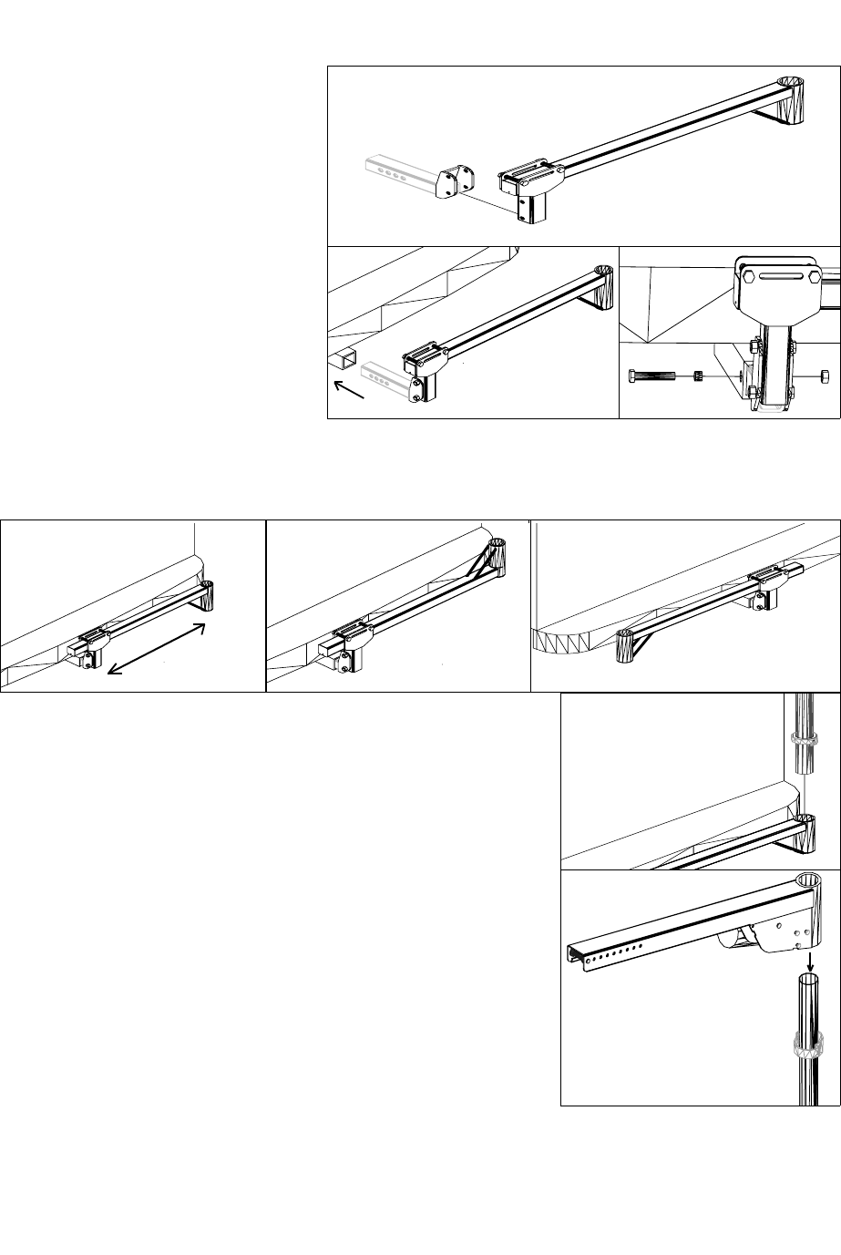
3. The Arm Assembly may be adjusted sideways (Fig. 1), inverted (Fig. 2), or switched to a driver side
application (Fig. 3).
Fig. 1 Fig. 3 Fig. 2
5. Place the power frame on the top of the post. Rotate the frame
so that it drops down into the rotation limit collar at the top of the
post.
Caution: Carefully read and
follow each of the following steps each
time you assemble the lift. Failure to
do so can result in damage to the lift,
vehicle, chair, or injury to the installer/
operator.
1. Unpack the AL065’s shipping box
and identify the Arm Assembly with
hitch adapter bolted to it hitch.
2. Insert the Hitch Adapter into the
vehicles trailer hitch. Bolt the Hitch
Adapter to the hitch using the 1/2-13 x
3-1/2 bolt, nut and pinch bolt tube. Be
sure to tighten the bolts sufficiently.
4. Insert the post into the hole at the end of the Arm Assembly.
The post does not have a specified top or bottom so either end
may point up. The post is equipped with two rotation limit collars.
These collars prevent the lift from rotating too far. Rotate the post
so that the lower collar drops down around the arm assembly.
Caution: Pinch points exist at both rotation limit collars.
Always stay clear of these areas.
6. The arm assembly, rotation limit collars, and power frame have
a strip of red material on them. To ensure that the lift is assembled
correctly, rotate the power frame and vertical post until all of the
red stripes line up vertically.
Installing the AL065


