


Installation Instructions
4 313848C
Installation Instructions
Pressure Relief Procedure
Follow this pressure relief procedure whenever you are
instructed to relieve pressure or need to check or ser-
vice equipment.
1. Turn off power (air, electric, hydraulic) to lube supply
pump.
2. Turn off air supply to air manifold.
3. Using a wrench, slowly loosen fluid inlet fitting.
4. Using a wrench, slowly loosen each outlet port fit-
ting.
5. Using a wrench, slowly loosen air inlet fitting.
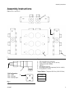
Assembly Instructions
NOTE: The Air Over Oil Manifold is designed to mount
to a standard Graco MSP divider valve. For instructions
on how to use an MSP divider valve, refer to instruction
manual 312497.
The Air Over Oil Manifold uses one-way air injectors to
inject air into each of the individual divider valve lube
outlet ports. Each air injector assembly is internally
checked to prevent oil from entering the air supply sys-
tem.
The Air Oil Valve does not utilize common porting
between the lube outlets, therefore each outlet is both
pneumatically and hydraulically independent.
An air pressure sensor is provided to monitor for any
blockage or breaks in the air line.
The MSP divider valve can be used with a cycle indica-
tor to monitor for proper oil lube cycles or blockage in
any of the lubrication lines.
1. Remove alternate outlet port plugs from divider
valves.
2. Loosen valve mounting socket head cap screws.
3. Place air over oil manifold over valves and hand
tighten all air injectors to seat manifold on the valve
stack. Then tighten air injectors with a wrench in a
star pattern until all o-rings are seated in o-ring
ports of valve and manifolds.
NOTE: The correct order is provided in chart on
page 3.
4. Using valve mounting screw access ports, torque all
valve mounting socket head cap screws to 8 - 9
foot/pounds (10.8 - 12.2 N•m).
5. The air supply may be induced into manifold using
available ports, A1, A2, A3, or A4.
6. The air pressure sensor may be connected to any
available port not connected to the air supply. This
device warns of any blockage or breaks in the air
line.
NOTE:
• Always use an air line filter of 40 micron or better to
remove dirt and moisture from the compressed air
supply.
• Install an air regulator to allow pressure adjustment.
Start Up Instructions
• System must be pre-filled with 100 psi (0.69
MPa, 6.9 bar) of air pressure. Once system is
pre-filled and oil is being emitted from each dis-
tribution line, system air may be reduced to final
operating pressures.
• Minimum operating air pressure is 45 psi (0.31
MPa, 3.1 bar).
• Air pressure sensors are factory set to 35 psi
(0.24 MPa, 2.4 bar) (Models 24B237, 24B239,
24B240, 24B241 only).