


General
Weight: 150 g (5.3 oz)
Overall Length: 53.8 inch (1.36 m)
Battery: Standard 9 V battery (NEDA #1604,6F22,006P)
Battery Life: 600+ hours, typical (Alkaline Battery), 6.5 V minimum
Output Termination: Standard 0.75-inch spaced double banana plug
Probe Material: Glass-filled valox
Probe Size: 0.6 inch maximum diameter
Tip Material: Nickle Plated Copper
Tip Size: 0.31 cm (0.12 inch diameter)
Operating Notes
The following paragraphs are intended to familiarize the operator with
the 80T-150UA. The operator should read these paragraphs before
attempting to operate the probe.
Probe Limitations
The 80T-150UA probe is constructed of a highly durable plastic and is
suitable for measuring the temperature of liquids, gases, and solid
surfaces up to 150 °C. When measuring temperature, observe the
following precautions to prevent damage to the probe:
1. Do not expose the probe end (probe tip plus about 2 inches of the
probe body) to temperatures exceeding +150 °C (+302 °F). The
remainder of the probe body should not be exposed to temperatures
above +70 °C (+160 °F).
2. Do not expose the probe end (probe tip plus about 2 inches of the
probe body) to temperatures below -50 °C (-58 °F). The remainder
of the probe body should not be exposed to temperatures below
-40 °C (-40 °F).
3. For liquid measurements, recommended applications range from
water, lubricants, and fuels to most solvents. Liquids as shallow as
1.27 cm (0.5 inch) can be measured since the temperature sensor is
inch the probe tip.
XWWarning
To avoid electrical shock, do not use this instrument when
voltages exceeding 60 V dc or 30 V ac rms (42.4 V peak )
are present. The probe tip is electrically connected to the
output terminals.
WCaution
Long-term exposure of the probe to corrosive
environments will result in pitting and deterioration of the
aluminum probe tip. If equipment is used in a manner not
specified by the manufacturer, the protection provided by
the equipment may be impaired.
Error Sources
When the probe tip is applied to a solid surface, it draws or sinks heat
from the surface. Therefore, if the measured surface has a low mass
(e.g., a transistor case), the indicated temperature may be lower than
the actual temperature.
Similarly, a steady-state error or gradient exists between the measured
surface and the sensing device in the probe tip. This is due to the flow of
heat from the measurement surface to the probe body. The effect of the
steady-state error increases as the differential between ambient and
surface temperature increases.
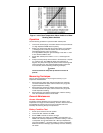
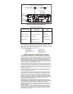
To determine the actual surface temperature of a device, both the heat-
sinking and steady-state errors must be considered. The correction curve
given in Figure 1 approximates the effect of both error sources on TO-3,
TO-5, and TO-18 transistor cases.