


Operator Safety
W
Indicates the operator must refer to an explanation in this
manual.
Indicates terminals at which lethal voltages may exist.
Warning
• To avoid damage or electric shock:
• Use within ratings and under dry (no
condensation) conditions.
• The 80K-40 user should be familiar with, and
exercise, all possible high voltage safety
practices.
• When making a measurement, never make body
contact with the probe tip or the red portion of the
probe. Always hold the probe by its black handle.
• Before making a measurement, make sure that
the tab side of the output connector is connected
to the voltmeter’s low input terminal.
• The clip lead must be attached to earth ground.
Voltmeter Compatibility
Accuracy of the meter is not included in the accuracy of the
probe, and must be added to the probe accuracy to determine
system accuracy.
The 80K-40 is mechanically compatible with any ac or dc
voltmeter or multimeter capable of accepting a standard spaced,
0.75" (19mm) double, banana plug, having standard, .160" (4mm)
plugs.
The 80K-40 probe is electrically compatible with any ac or dc
voltmeter or multimeter that has an input impedance of 10 MΩ
±1%. Voltmeters or multimeters with other input impedances
require the use of an external shunt or a correction factor to
obtain an accurate measurement. Higher impedance voltmeters
or multimeters should be equipped with a shunt, and lower
impedance voltmeters or multimeters should be assigned
correction factors. Applicable formulas follow:
a. The following formula is used to determine the value of an
external shunt resistor (meter impedance >10 MΩ):
Rs
Rm x 10
Rm 10
=
−
Where: Rs = Shunt resistance in MΩ
Rm = Voltmeter input impedance in MΩ (>10 MΩ)
Example: If RM = 20 MΩ,
Rs
20 x 10
20 10
=
200
10
=2.0M=
−
Ω
b. Use the following formula to calculate a correction factor
(meter impedance <10 MΩ):
Cf
1.11 + Rm
1.11 x Rm
=
Where: Cf=Correctionfactor (multiplier for meter reading)
Rm = Voltmeter input impedance in MΩ
Example: If Rm = 1 MΩ,
Cf
1.11 + 1
1.11 x 1
=
2.11
1.11
=1.901=
Therefore: A meter reading of 0.526 volts represents an
input of: 0.526 x 1.901 = 1 or 1 kV.
Circuit Loading
The 80K-40 represents a 1000 MΩ load to the circuit being
measured, or 1 µA per 1 kV. Table 1 shows the circuit loading
and input/output characteristics of the probe over its
measurement range.
Table 1. 80K-40 Circuit Loading and Input/Output Characteristics
Input Voltage Loading Current Output Voltage
10V
100V
1 kV
10 kV
20 kV
30 kV
40 kV
10 nA
100 nA
1µA
10 µA
20 µA
30 µA
40 µA
10 mV
100 mV
1V
10V
20V
30V
40V
Operation
Use the following procedure to operate the 80K-40:
1. Select and energize a compatible voltmeter.
2. Equip the voltmeter with a suitable shunt, if required.
3. Select an appropriate voltage range (1 volt reading per 1000
volt input. See Table 1).
4. Connect the probe’s output leads to the voltmeter input
terminals.
5. Connect the probe’s clip lead to ground. See OPERATOR
SAFETY.
6. Connect probe tip to circuit being measured and observe
voltmeter reading. Apply correction factor to reading when
necessary.
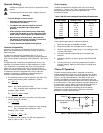
Theory Of Operation
The 80K-40 High Voltage probe, is designed to extend the
voltage measurement range of an ac/dc voltmeter up to 40,000
volts. Electrically, the probe is a passive attenuator as shown in
Figure 1. Its high input impedance (1000 MΩ), as well as its
accuracy and stability characteristics are achieved through the
use of special thick film resistors. When the probe is connected to
a voltmeter with a 10 MΩ input resistance the probe becomes an
accurate 1000:1 divider. Notice that the divider depends upon a
ground lead to complete the low side of the circuit path.
Therefore, this connection must always be secure before
attempting a voltage measurement. Otherwise, instrument
damage or a shock hazard will result.
Probe Tip
Ground
Lead
Replacement Resistor Kit
PN 939335
10MΩ
80K-40 DC Voltmeter
HI
LO
Figure 1. 80K-40 Simplified Circuit Diagram