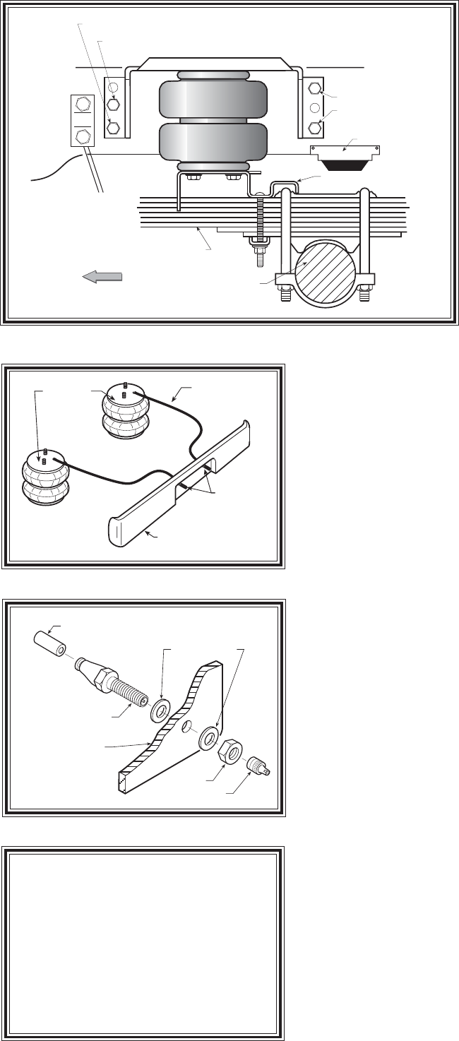
LOWER BRACKET
LEAF SPRING STACK
AXLE
FRONT
Left side shown
(Drivers side)
JOUNCE BUMPER
EXISTING 5/8 DIA. HOLE
HOLE TO BE DRILLED
HOLE TO BE DRILLED
EXISTING 5/16 DIA. HOLE
AIR HOSE
INFLATION
VALVES
BUMPER
AIR
SPRINGS
STEP 1 - PREPARE THE VEHICLE
Make sure that the vehicle is on a solid
level surface. Take necessary safety pre-
cautions such as using wheel chocks when
working under your vehicle. This vehicle
does not have to be jacked up to install the
kit. Remove the positive battery cable.
STEP 2 - PREASSEMBLE THE
RIDE-RITE KIT
Select one air helper spring from your
kit and an upper bracket. Align the studs
on the air spring with the holes on the
upper bracket making sure the air inlet
hole can be seen through the slot in the
upper bracket see Figure "A". Use the
3/8"-16 flange lock nuts to secure the up-
per bracket to the air spring. Install the air
fitting as shown in Figure "A". Tighten the
air fitting securely to engage the orange thread sealant. Point the
elbow fitting in the direction of the inflation valve location. Refer to
Step 6 for inflation valve installation. Position the lower bracket as
shown in Figure "A" & "B". Fasten the lower bracket to the air helper
spring using two 3/8"-16 x 3/4" hex bolts.
STEP 3 - PRE-FIT MARK AND DRILL HOLES
Position the assembly on the frame as shown in Figure "A" & "B".
The upper bracket has three holes in each flange. Only two holes in
each flange will be used for mounting to the frame. Two mounting
holes are matched with existing holes in the frame see Figure "A" &
"B". One hole is 5/16" in diameter and will need to be drilled out using
a 7/16" diameter drill bit. Before drilling the holes make sure all
electrical, brake and fuel lines are cleared from the path of the drill.
Damage to lines can be avoided by inserting a piece of wood between
the frame rail and any lines in the path of the drill. The other hole is
5/8" diameter and will require the use of a 3/8" special washer behind
the frame rail. The 3/8" diameter washers should also be placed on the
inside of the frame rail behind each upper bracket fastener. Bolt the
upper bracket to the existing holes in the frame as shown in Figure
"A". Using the bracket as a template drill a 7/16" hole in each of the
upper flange holes shown in Figure "A" & "B". Complete the attachment
of the upper bracket to the frame using the 3/8"-16 x 1-1/2" hex bolts,
washers and nuts.
STEP 4 - LOWER BRACKET ATTACHMENT
Mount the lower bracket to the leaf spring stack by sliding the lower
bracket to the leaf spring retainer see Figure "B". Make sure the lower
bracket is placed so that the retainer and leaf spring "U"-bolt is captured
by the lower bracket as shown in Figure "B". Install 3/8"-16 x 5-1/2"
carriage bolts in the square holes of the lower bracket. The lower bracket
is then secured by a bracket strap which is placed under the leaf spring
stack and retained with 3/8"-16 flanged lock nuts.
STEP 5 - INSTALLATION TO THE PASSENGER'S SIDE ASSEMBLY
Follow steps 1-4 for assembly and installation of the passenger's
side assembly. Reverse any orientations when assembling and in-
stalling the right, or passenger, side of the vehicle. Please note that
when installing the kit on the passenger's side of the vehicle, the upper
bracket will locate again on the existing holes in the frame. However,
Figure "B"
AIR HOSE
PUSH-TO-CONNECT
INFLATION VALVE
FLAT WASHER
HEX NUT
VALVE CAP
BODY OF
VEHICLE
Figure "D"
Figure "C"
NOTE:
Once the air helper springs are
installed, it is recommended that the
vehicle not be lifted by the frame, as
over-extension may occur, resulting in
damage to the air helper springs. How-
ever, should it become necessary to raise
the vehicle by the frame, deflate both air
helper springs completely.


