Evolution UC-33 Advanced User Guide
1 6
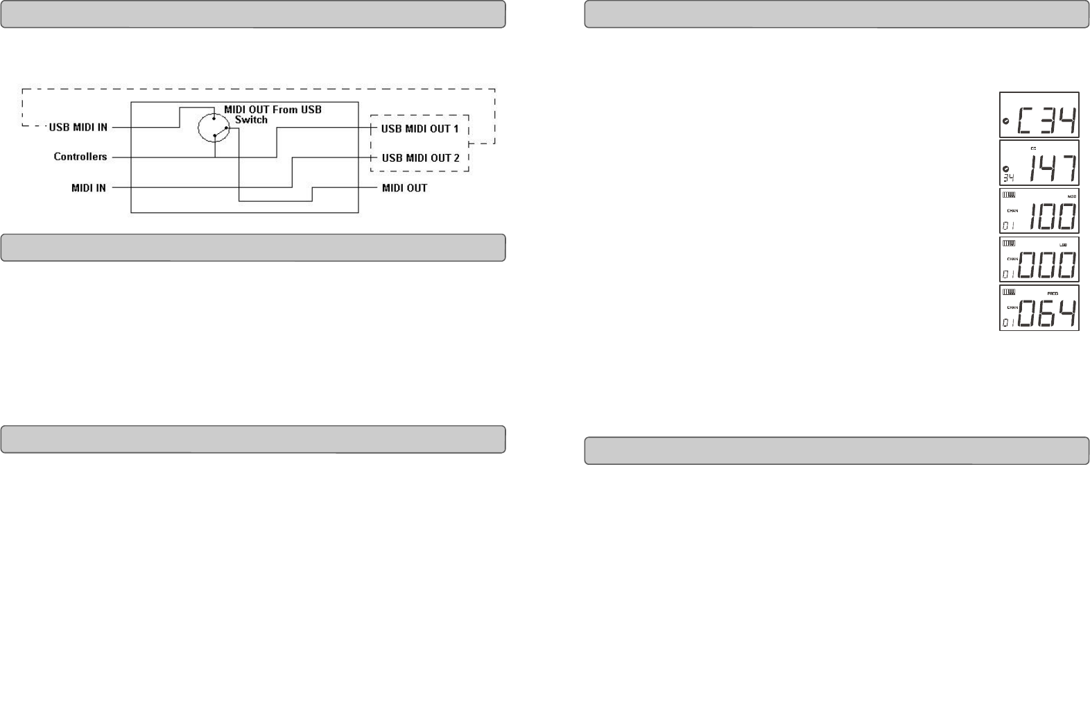
The MIDI IN & MIDI OUT ports have different uses depending on how you intend to
connect and power the UC-33. The diagram below shows the different routing
options.
The MIDI in plug can be used to interface another MIDI device to your PC, via the USB
port. Data received from this device will be transmitted via the UC-33 to the PC. This is
achieved using a second USB MIDI out. So, when you select the MIDI devices section of
your sequencer you will see two UC-33 USB MIDI Ins. The first of these is used to receive
the UC-33 controller data, the second is used to receive data from the other device con-
nected to the UC-33’s MIDI IN plug. So, the UC-33 is acting as a MIDI-to- USB interface
for the other MIDI device.
The UC-33 can of course also interface with other MIDI devices. By default (I.e. when you
switch the unit on), all controller data is sent out via the MIDI output as well as the USB
out.
If you want the MIDI output to act like a traditional USB-to-MIDI interface, just press the
two buttons (SELECT and ASSIGN) that activate the MIDI OUT from USB mode.
If you are using a host application which can pick up multiple input drivers, you will be
able to use the UC-33’s MIDI input and the UC-33 surface to record MIDI data and send
the whole lot out of the UC-33’s MIDI output.
Important note: The UC-33 is not a MIDI THRU device and as such, MIDI data received
at the UC-33's MIDI IN plug can never be sent directly to the UC-33's MIDI OUT plug.
However, if the UC-33 is connected via USB to a computer, data received at the MIDI IN
can be transmitted to the MIDI OUT plug, since the data is sent to the computer, and
received back from the computer. MIDI OUT FROM USB mode must be engaged for this
to occur.
MIDI In & MIDI Out Signal Flow Diagram
About The MIDI In Port
About The MIDI Out Port
Evolution UC-33 Advanced User Guide
1. Press SELECT and press the “0” button. The display will show that you
have selected controller 34.
2. Press ASSIGN and enter '147' this is the MIDI CC
number that corresponds to Note on/off mode, as shown in
Appendix B.
3. Press DATA MSB and enter a value of '100'. This means when
you press the button, a Note on message will be sent out
with a velocity of 100.
4. Press DATA LSB, and enter a value of '000'. This means when
you release the button, a Note off message will be sent out
5. Press the PROGRAM button and enter '064'. This will mean
you are sending out MIDI note 64 or E4, each time you
press the button. The MIDI note numbers are given in
Appendix D.
This button mode has many uses. You can use this mode to trigger
samples, control lighting equipment, play keyboard notes and much more.
Note: When you press the button in note mode, the LCD display will briefly
show the note velocity.
When transmitting SysEx messages, the individual control channel number does not
define a transmit channel, but a device ID. This is made clear since when you press
the CHANNEL button, the CC symbol will not be shown and there is no ’c’ in the 3
digit display.
Device ID’s range between 00 – 127. In most cases, you should set the device ID as
127. 127 means the SysEx message will be received by all devices.
Please note that the device ID for a Sys Ex message assigned to a controller can not
be changed using the Device ID buttons. These buttons are used for varying the
global device ID of the UC33.
Assigning A Note To A Button
About SysEx Messages & Device ID


