


Instruction Manual
IB-106-3081 Rev. 1.5
September 2002
Rosemount Analytical Inc. A Division of Emerson Process Management Maintenance and Service 5-1
Model 3081FG
SECTION 5
MAINTENANCE AND SERVICE
Install all protective equipment covers
and safety ground leads after equip-
ment repair or service. Failure to in-
stall covers and ground leads could
result in serious injury or death.
Disconnect and lock out power before
working on any electrical components.
5-1 MODEL 3081 ELECTRONICS
REPLACEMENT
Before replacing any electronic components,
verify that the power to the Model 3081 Trans-
mitter is removed. Refer to Table 8-1 for re-
placement part numbers.
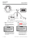
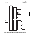
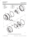
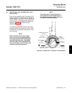
a. Display Board Replacement
Use the following procedure to replace dis-
play board (11, Figure 5-1).
1. Loosen screw (14) until cover lock (15)
disengages from the knurled surface of
circuit end cap (13).
2. Remove circuit end cap (13).
3. Remove three screws (12) retaining
the electronics in place.
4. Lift display board (11) and disconnect
the ribbon cable connector between
the display board and the CPU board
of PC board stack (10).
5. Using a replacement display board,
connect the ribbon cable connector
between the display board and the
CPU board of PC board stack (10).
Ensure the cable connector is fully
seated.
6. Reposition display board (11) on the
standoffs. Rotate the display board 90
degrees either way as desired.
7. Install and tighten all three screws (12).
8. Install circuit end cap (13).
9. Tighten cover lock screw (14) until
cover lock (15) engages knurled sur-
face of circuit end cap (13).
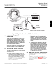
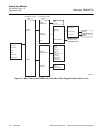
b. PC Board Stack Replacement
PC board stack (10, Figure 5-1) is com-
posed of the CPU board and the analog
board. Use the following procedure to re-
place these boards as a set.
1. Loosen cover lock screw (14) until
cover lock (15) disengages from the
knurled surface of circuit end cap (13).
2. Remove circuit end cap (13). Remove
three screws (12).
3. Lift display board (11) and disconnect
the ribbon cable connector between
the display board and the CPU board
of PC board stack (10).
4. Lift the CPU board from housing (1) by
the standoffs.
5. Remove two screws (4) and lockwash-
ers (3). Lift terminal block (6) until the
analog board is unplugged from the
terminal board.
6. Reinstall terminal block (6), lockwash-
ers (3), and screws (4).
7. Lift the analog board from housing (1)
by the standoffs.
8. Install replacement PC board stack
(10) into housing (1). Carefully seat the
analog board onto housing pins. Press
firmly on the CPU board standoffs to
ensure good contact.
5