


4 Chapter 2
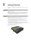
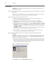
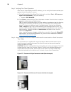
4. Place your thumbs on the top surface of the opposite end where the three screws
were removed. With a continuous motion, push firmly downward and towards the
back panel (pushing down unlatches the hooks under the cover). The cover will shift
approximate 1/4 inch to hang over the back panel. (a) Grasp the overhanging cover
edge and raise the edge about 1-1/2 inches, and then (b) pull the cover out towards
the back panel at the same angle to free the opposite end of the cover from the
remaining hooks, as shown in Figure 3.
Figure 3 Removing the cover
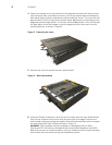
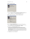
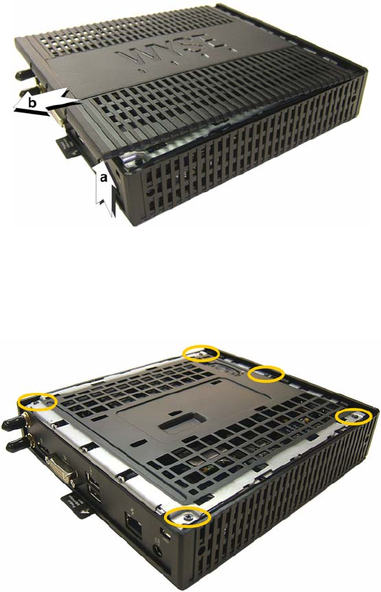
5. Remove the cover to expose the main-board shield.
Figure 4 Main-board shield
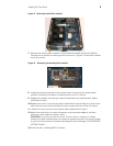
6. Using the Phillips Screwdriver, remove the five screws from the main-board shield
(four corner screws and one screw mid-way along the front edge). Remove the
main-board shield and unplug the speaker wires (red wire and black wire) to expose
the main board and Flash module as shown in Figure 5.
WARNING: Flash modules may be susceptible to damage by Electro-Static
Discharge (ESD). All industry-standard cautions should be followed to avoid ESD.
Before you remove or install a module, touch any metal part of the chassis and keep
that contact with the chassis during the installation process.