


Installation Instructions
Model FSB-4101
3
NOTE: If the flat panel display has a table stand
attached, remove existing stand.
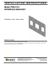
Flush Mount Installation
1. Secure the Interface Bracket to the Display using 1/8"
Nylon Spacers and M4 x 12mm screws
(see Figure 2).
NOTE: Length of mounting screws is dependant
upon length of spacer used.
Figure 2:
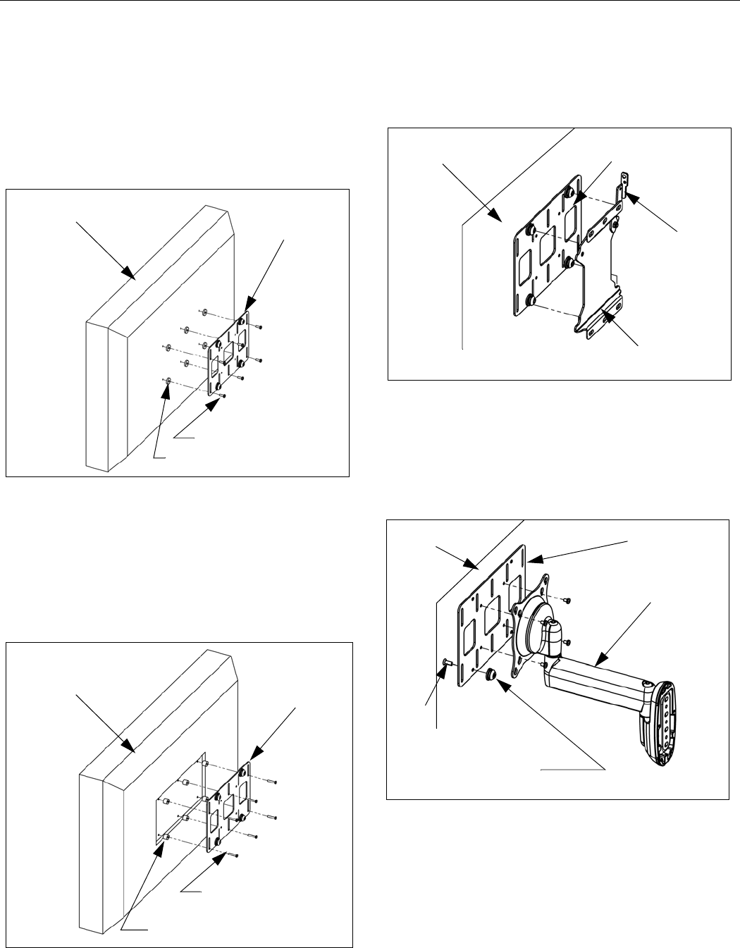
Recessed Mount Installation
1. Place four Nylon spacers (3/8" or 3/4" as necessary)
over four mounting holes in Display (see Figure 3).
2. Secure the Interface Bracket to the Display using M4
x 20mm or M4 x 30mm screws depending upon
spacer used. (see Figure 3).
Figure 3:
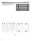
Mount to Q2 System
1. Install flat panel display, with interface plate attached,
on Q2 mount (see Figure 4).
2. Move latching flag of Q2 mount to secure display.
Figure 4:
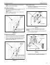
Conversion to VESA 75mm Mounting/Centris®
Mounts
1. Remove Phillips head screws and mounting buttons
from the interface bracket.
Figure 5:
2. Using M4 x 6mm screws, attach the interface bracket
to any VESA 75mm x 75mm mounting device.
Display
Interface
Bracket
1/8" Nylon Spacers (6)
M4 x 12mm Screws(6)
Display
Interface
Bracket
3/8" or 3/4" Nylon Spacers(6)
M4 x 20mm Screws(6)
M4 x 30mm Screws(6)
Display
Interface
Bracket
Q2 Mount
Latching Flag
Display
Interface
Bracket
Mounting Button
Phillips Head
Screw (4)
VESA Mount