1
2
+
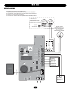
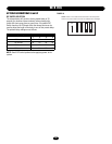
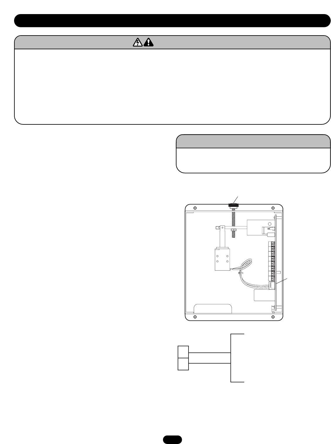
24Vdc from an Approved UL 1481
Regulated Power Supply
with Battery Backup
–
5
WIRING
WIRING INSTRUCTIONS
Verify wiring configuration with that recommended by door
manufacturer for use of this product with specific door and
accessories being utilized. 18-gauge wire is recommended.
1. Turn off power supply sources for the release device as well as
the door operator, if applicable, before beginning.
2. Verify voltage rating of release device to power source being
utilized. Voltage is indicated on the side of the unit. Verify that
power is disconnected before proceeding.
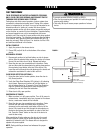
3. Connect 24Vdc power to terminal board positions 1 and 2
(Figure 2). Observe proper polarity. 24Vdc power input from an
approved UL 1481 regulated power supply with battery backup.
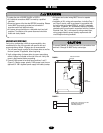
To reduce the risk of SEVERE INJURY or DEATH:
• ALL electrical connections MUST be made by a qualified
individual.
• Disconnect power at the fuse box BEFORE proceeding. Release
device MUST be properly grounded and connected in
accordance with local electrical codes.
• ALL power wiring should be on a dedicated circuit and well
protected. The location of the power disconnect should be
visible and clearly labeled.
• ALL power and control wiring MUST be run in separate
conduit.
• Installation of ALL wiring and connections, including Class 1
and Class 2 circuits, shall be performed in accordance with,
but not limited to, the latest NFPA, UL and N.E.C. standards
and codes. In addition, ALL installations subject to Canadian
standards shall be performed in accordance with the Canadian
Electrical Code, Part I, with respect to wiring material type,
wiring gauge related to power capacity requirements and
circuit length and wiring methods.
WARNING
CAUTION
WARNING
WARNING
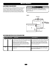
Option
DIP Switch
Mechanical Reset
Plunger
FIGURE 2
FIGURE 1
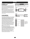
To prevent DAMAGE to the circuit board, ALL connections from
terminals 3 through 16 MUST be dry contact type.
WARNING
CAUTION
WARNING
WARNING


