


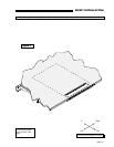
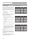
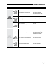
SYSTEMS DESCRIPTIONS
HAZARD
CAUTION!
ESD
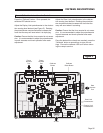
K1
K2
U1
D12
51
U9
76
26
1
R10
R11
U13
U14
U15
1413
2
1
4 7
6
5
11 12
J7
3
109
8
J4
J5
100218-
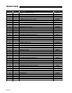
REVISION
U2
U8
U11
U12
J10
1 9
2 1010
9
2
1
F1
J1
U7
U5
Y1
U6
U3
61
41
21
1
U4
J9
5 3
J8
4 12
AZ987-2C
AZ987-2C
D13
C20
D15
D16
D14
C19
D7
D2
AZ987-2C
F3
J6
12
6
7
1
J3
D17
D18
+
+
C24
Q5
S1
S2
1
J14
2 3
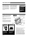
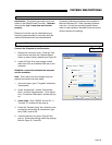
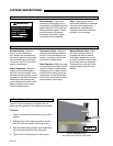
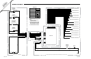
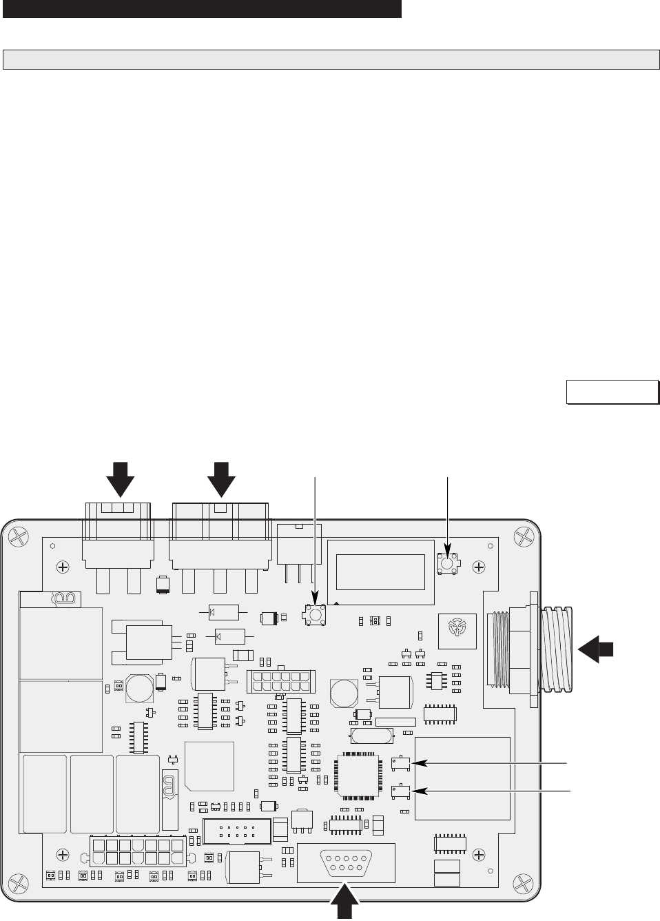
Manual Calibration Instructions for Controller
Figure S
Power
Harness
Port
Ramp
Harness
Port
Data
Harness
Port
J9 Port
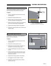
Calibrate
Button
Stow Limit
Potentiometer
Deploy Limit
Potentiometer
Calibrate
Reset Button
Press the “Calibrate” button. Once pressed, the
calibrate LED should turn on.
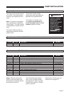
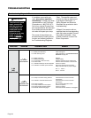
Adjust the Deploy Limit potentiometer to the obstruc-
tion sensing level desired (see Figure S). Rotating
the potentiometer counterclockwise increases the
force that the ramp will exert when it is deploying.
Caution: Ensure that the force exerted is not exces-
sive. It is recommended to adjust the potentiometer
in small amounts and check operation after each
adjustment.
Adjust the Stow Limit potentiometer to the obstruc-
tion sensing level desired. Rotating the potentiom-
eter counterclockwise increases the force that the
ramp will exert when it is stowing.
Caution: Ensure that the force exerted is not exces-
sive. It is recommended to adjust the potentiometer
in small amounts and check operation after each
adjustment.
Once the desired force levels are reached, press the
“Calibrate” button a second time to store the set-
tings. Ensure the calibrate LED is off before return-
ing the ramp to service.
Page 35